


CSMS-R/RRS: 0800000756, 0235-14 / Status: 2 / Issue date: 2014-08-05
33
The following are 2 examples of a
length estimation:
Example 1
of a length estimation:
Power supply = 24 V
5 CSMS in the system
Output current
of the last CSMS = 2 • 10 mA
Cable cross section 0.25 mm
2
Maximum cable length = 160 meters
Example 2
of a length estimation:
Power supply = 24 V
10 CSMS in the system
Output current
of the last CSMS = 2 • 20 mA
Cable cross section 0.25 mm
2
Maximum cable length = 80 meters
Teaching in the actuator
The actuator of a CSMS unit has a non-modifiable safety
code. This code must be submitted to the CSMS and
permanently saved in the CSMS. This is already done in
the CSMS sets.
In case of CSMS or actuator single orders, the initial
programming has to be done with the BERNSTEIN program-
ming tool (artice number 6075989056). The same applies to
the identification of a substitute actuator.
Short description:
The actuator must be exactly in front of the CSMS sensor.
See page 24, approach direction A1. The teach adapter
will be switched in series between the power supply and
the CSMS sensor to be taught in.
After the CSMS sensor connection is completed and
the voltage is impressed, the red LED of the CSMS sensor
lights up.
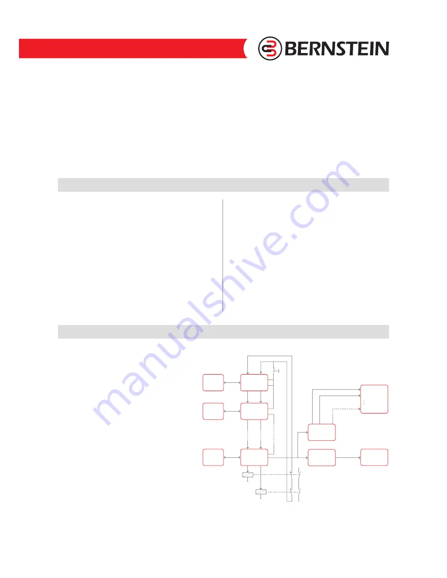
CSMS diagnostic interface
Products that might be used for the application:
●
6075989031 – CSMS DIAGNOSE STANDARD 8
●
6075989032 – CSMS DIAGNOSE STANDARD 16
●
6075989033 – CSMS DIAGNOSE PROFIBUS
The CSMS has a serial diagnostics interface with
one input (Di) and one output (Do).
The diagnostic interface is used for transmission
of internal safety-related status information.
A detailed description is included with the device
manufacturer’s instructions.
The use of the diagnostic interface is optional.
With this diagnostic interface (for article see also table
on page 36), the user can see for example, which
protective guards are open or closed. This information
is transmitted, depending on the diagnostic device,
either electronically via PNP outputs or via gateway
to the Profibus. Via a bus interface, a large amount of
additional information from the CSMS can be directly
transmitted to the controller.
Sensor 1
Actuator 1
Actuator 2
Actuator n
Sensor 2
Sensor n
EDM
CSMS
Diagnostic
Profibus
Load circuit
Start-
Button
Relay 1
Relay 2
PLC
Input
PLC with
Profibus
Profibus
1
8/16
2
CSMS
Diagnostic
Standard
Fig. 28
The green LED on the teach adapter lights up when the
CSMS sensor has read out the actuator. The button on the
teach adapter should then be pressed. After the learning
procedure has been successfully completed, the green LED
of the CSMS sensor lights up. The teach adapter must then
be removed. For future operation, the system must be dis-
connected from the power supply for at least 2 seconds.
Potential sources of error if the learning procedure has not
been successfully completed.
●
Actuator and CSMS sensor not positioned properly
●
Plug connectors not connected together properly
A detailed description for programming the safety code
is included with the programming tool.


