background image

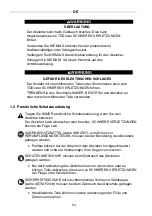
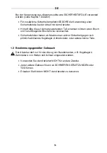
 DE  

65

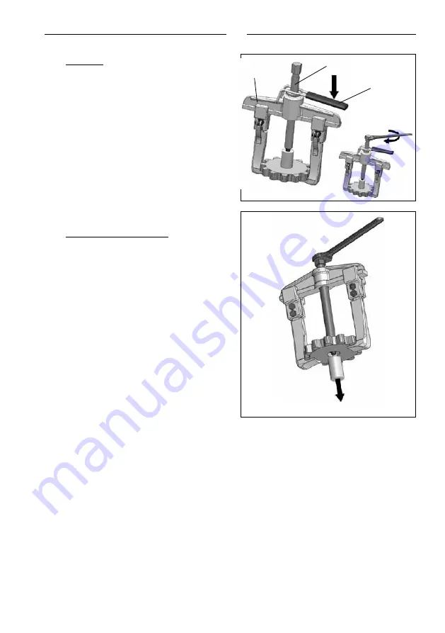
Typ 1.08
Drücken Sie den Entriegelhebel (I) zur 

Traverse (A) und schieben Sie die 

Spindel (B) in die Traverse hinein bis 

sie auf der Welle aufliegt. 
Danach lösen Sie den Entriegelhebel (I) 

und verwenden ein passendes 

Antriebswerkzeug, z. B. einen 

Maulschlüssel um einen leichten Druck 

auf dem Werkstück aufzubauen. 

Typ 1.06, 1.07 und 1.08

Schrauben Sie so lange weiter, bis sich 

das abzuziehende Teil komplett löst 

A

Содержание 895342

Страница 1: ...Bedienungsanleitung Zweiarmabzieher Satz Artikelnummer 895342 Sprachen en fr de es BERNER_Bedienungsanleitung_Zweiarmabzieher Satz_76720 PDF _de pdf 2016 11 10 ...

Страница 2: ...52 68 www gedore com AVOID INJURY You MUST read and understand these Operating Instructions before using the pullers EVITE LESIONES Usted TIENE que leer y entender este manual antes de usar los extractores EVITER TOUTE BLESSURE Vous DEVEZ lire et comprendre ce mode d emploi avant d utiliser les extracteurs VERMEIDE VERLETZUNGEN Sie MÜSSEN diese Betriebsanleitung lesen und verstehen bevor Sie die A...

Страница 3: ...ent 5 2 Product Description 6 3 Preparing the Puller for Use 7 3 1 Assembling the Spindle 7 3 2 Assembling Pulling Legs on the Traverse 7 3 3 Clamping Pulling Legs on the Traverse 9 4 Safe Use 11 4 1 Settings for Pulling 12 4 2 The Pulling Process 13 5 Removing the Puller 15 6 Care and Storage 16 7 Optional Accessories 16 8 Maintenance and Repair 16 9 Environmentally Friendly Disposal 16 10 Techni...

Страница 4: ...Operating Instructions prior to using the puller The Operating Instructions MUST be available to the employees for reference at all times 1 1 Safety Warnings Throughout this manual WARNING CAUTION NOTICE and the SAFETY ALERT SYMBOL will be used Indicates a hazardous situation which if not avoided could result in death or serious injury Indicates a hazardous situation which if not avoided could res...

Страница 5: ...es SAFETY GLOVES must be worn when using the puller The puller can slip or break during use causing SERIOUS INJURY to your fingers and hands SAFETY SHOES with slip resistant soles and steel toe caps see ASTM F2413 05 must be worn when using the puller Falling parts can cause SERIOUS INJURY to your feet and toes PROTECTIVE SAFETY COVERS should be utilized when using the puller see Section 7 Optiona...

Страница 6: ...nsafe use of the puller Improper handling can result in SERIOUS INJURY or DEATH ALWAYS check the puller for damage before use ALWAYS replace damaged or worn parts before use ALWAYS use only GEDORE original spare parts and accessories NEVER use electric or pneumatic torque multipliers or impact wrenches NEVER use electric pneumatic or percussion drivers NEVER heat the puller NEVER modify any parts ...

Страница 7: ...g legs D Clamps E Screw F Drive hex G Spindle point H Nut Type 1 08 with quick adjustment A Traverse B Spindle C Pulling legs D Clamps E Gripping lever F Drive hex G Spindle point H Knurled nut I Unlock lever for quick adjustment C B D E H F B F A C G A D C E H G I C Diagram depicts Type 1 06 ...

Страница 8: ...2 Assembling Pulling Legs on the Traverse PINCH HAZARD Take the following precautions to prevent pinch injuries to your fingers when sliding the pulling legs on the traverse ALWAYS perform the assembly on a work bench DO NOT grasp in between the pulling legs when sliding the pulling legs on the traverse with your fingers Hold the traverse horizontally so that the pulling legs cannot slip down The ...

Страница 9: ... is explained in the following instructions Follow the instructions for the model you have purchased Type 1 06 and 1 07 Pulling legs with screw clamp Loosen the screw connection E H until you can push the pulling legs onto the traverse easily Push the pulling legs C onto the traverse A E H A C ...

Страница 10: ...EN 9 Type 1 06 E 1 07 E 1 08 Pulling legs with gripping lever Open the gripping lever E on the pulling leg C to loosen the clamp D Push the pulling legs C onto the traverse A E D C A C C ...

Страница 11: ...screw connection E H slightly The pulling legs C can still be adjusted using manual pressure Type 1 06 E 1 07 E 1 08 Pulling legs with gripping lever To adjust the clamp properly 1 Pull the clamping lever up E into a horizontal position 2 Tighten the knurled nut H until you feel slight resistance To tighten the clamps D on the traverse Push the gripping lever E down against the pulling legs C D E ...

Страница 12: ...h a larger capacity DO NOT hit the part with a hammer in an attempt to jar it loose ALWAYS use a Protective Safety Cover when using the puller For added safety GEDORE highly recommends the use of a Protective Safety Cover shown in photo when using the puller Cover the puller setup and part to be pulled with the Protective Safety Cover before applying force High forces exerted on the part being pul...

Страница 13: ...12 inches 3 mm from the clamps D to the end of the traverse A BEFORE pulling take the following safety precautions Position the pulling legs C so that they are in contact with the part to be pulled Firmly tighten the pulling legs C so that the spindle operates centrally along the axis of the puller Position the spindle D with the spindle point G at a 90 angle directly on the part to be pulled Corr...

Страница 14: ...g Process During the pulling process puller parts and component parts can fall or suddenly detach causing INJURIES ALWAYS take the following precautions to prevent INJURY Wear personal protective equipment see Safety Section 1 2 Secure component parts and pullers from falling Types 1 06 and 1 07 Screw the spindle B on hand tight and then use a suitable drive tool such as a wrench to build up sligh...

Страница 15: ...pindle B into the traverse until it seats on the shaft Release the unlock lever I and use a suitable drive tool such as a wrench to build up slight pressure on the component part Types 1 06 1 07 and 1 08 Continue screwing until the part to be pulled is completely loose B I A ...

Страница 16: ... maximum force has been applied and the part has not moved use a puller with a larger capacity Cover the puller setup and part with a protective safety cover before applying force High forces exerted on the part being pulled can cause breakage and flying debris Protective Safety Cover available at www gedore com part number 5 10 If the part to be pulled does not come loose unscrew the spindle B wi...

Страница 17: ...l and Automotive Catalogs Protective Safety Cover Part No 5 10 Hydraulic Pressure Spindle Part No 1 06 HSP Pulling Legs for various applications Additional hazards and risks may be associated with using accessory parts with your puller To AVOID INJURY you must read and understand the Operating Instructions or Safety Information provided with the accessory part before using it with your puller 8 Ma...

Страница 18: ...11 130 2 75 70 7 08 180 M14x1 5 x 140 3 2 64 1 2 1 06 2A 7 87 200 3 54 90 10 23 260 G1 2 x 210 1 06 HSP1 5 7 71 3 5 1 06 3A 13 77 350 4 92 125 16 53 420 G3 4 x 280 1 06 HSP2 7 5 18 07 8 2 1 07 1 3 54 90 2 75 70 5 51 140 M14x1 5 x 140 3 3 08 1 4 1 07 2 6 29 160 3 93 100 8 66 220 G1 2 x 210 1 06 HSP1 5 7 93 3 6 1 07 3 9 84 250 3 93 100 15 74 400 G3 4 x 280 1 06 HSP2 7 5 20 5 9 3 1 07 1A 5 11 130 3 1...

Страница 19: ...n del producto 23 3 Preparación del extractor para usarse 24 3 1 Armado del husillo 24 3 2 Armado de las patas de extracción sobre el travesaño 24 3 3 Inserción de las patas de extracción en el travesaño 26 4 Uso seguro 28 4 1 Ajustes para la extracción 29 4 2 El proceso de extracción 30 5 Retiro del extractor 32 6 Cuidado y almacenamiento 33 7 Accesorios opcionales 33 8 Mantenimiento y reparación...

Страница 20: ...urarse de que los empleados que lo usen hayan leído y entendido estas instrucciones de manejo antes de usarlo Las instrucciones de manejo DEBEN estar a disposición de todos los empleados en todo momento para que las consulten 1 1 Advertencias de seguridad En todo este manual se usan las palabras ADVERTENCIA PRECAUCIÓN AVISO y el SÍMBOLO DE ALERTA DE SEGURIDAD Indica una situación peligrosa que si ...

Страница 21: ...quipo de protección personal Use SIEMPRE el equipo de protección personal cuando use el extractor El extractor puede resbalarse o romperse y causar LESIONES GRAVES Cuando use el extractor debe usar PROTECCIÓN OCULAR consulte ANSI Z87 1 diseñada para proteger contra OBJETOS PROYECTADOS Durante el trabajo con el extractor pueden proyectarse partículas y causar LESIONES GRAVES en los ojos Cuando use ...

Страница 22: ... proyección de partículas y dar como resultado LESIONES GRAVES Las protecciones de seguridad brindan máxima protección activa de seguridad contra rodamientos de bolas piñones motrices y otras piezas pequeñas que se desprenden repentinamente 1 3 Uso intencionado El extractor está diseñado para remover poleas rodamientos de bolas ruedas dentadas y otros componentes de flechas y ejes NO USE el extrac...

Страница 23: ...RE las piezas dañadas o desgastadas antes de usarlas Use SIEMPRE solamente partes originales y accesorios GEDORE NUNCA use multiplicadores de torque o llaves de impacto eléctricos o neumáticos NUNCA use atornilladores eléctricos neumáticos o de golpe NUNCA caliente el extractor NUNCA modifique ninguna parte del extractor especialmente las patas NUNCA se agache sobre la parte que está extrayendo NO...

Страница 24: ...F Atornillador hexagonal G Punta del husillo H Tuerca Tipo 1 08 con ajuste rápido A Travesaño B Husillo C Patas de extracción D Abrazaderas E Palanca de agarre F Atornillador hexagonal G Punta del husillo H Tuerca estriada I Desbloquee la palanca para ajustar rápidamente B B F G El diagrama muestra el tipo 1 06 F D A E H C C I A D H C C E G ...

Страница 25: ...e extracción sobre el travesaño RIESGO DE CONTUSION Tome las siguientes precauciones para prevenir lesiones por contusión en los dedos cuando inserte las patas de extracción en el travesaño Realice SIEMPRE el armado sobre una mesa de trabajo NO coloque los dedos entre las patas de extracción al insertarlas en el travesaño Sostenga el travesaño en posición horizontal para que las patas de extracció...

Страница 26: ...6 y 1 07 Patas de extracción con abrazadera de tornillos Afloje los tornillos y tuercas E H hasta que pueda empujar las patas de extracción para insertarlas con facilidad en el travesaño Empuje las patas C para insertarlas en el travesaño A Tipo 1 06 E 1 07 E 1 08 Patas de extracción con palanca de agarre Levante la palanca de agarre E que está en la pata de extracción C para aflojar la abrazadera...

Страница 27: ...as patas de extracción para que sienten bien Las patas flojas pueden deslizarse hacia fuera del travesaño y causar LESIONES GRAVES Tipo 1 06 y 1 07 Patas de extracción con abrazadera de tornillos Apriete ligeramente los tornillos y tuercas E H Las patas de extracción C pueden terminar de ajustarse presionando con la mano A C C C H E ...

Страница 28: ...tar la abrazadera correctamente 1 Levante la palanca E hasta que quede horizontal 2 Apriete la tuerca estriada H hasta que sienta cierta resistencia Para apretar las abrazaderas D sobre el travesaño Baje la palanca de agarre E hasta que tope con las patas de extracción C D E C H E E ...

Страница 29: ...olpee la pieza con un martillo para tratar de aflojarla Use SIEMPRE una protección de seguridad con el extractor Para mayor seguridad GEDORE recomienda ampliamente el uso de una protección de seguridad como se muestra en la imagen cuando use el extractor Cubra el conjunto del extractor y la pieza que va a remover con la protección de seguridad antes de aplicar fuerza Las fuerzas grandes que se eje...

Страница 30: ...zaderas D y el extremo del travesaño A Tome las siguientes precauciones de seguridad ANTES de hacer la extracción Coloque las patas de extracción C de modo que hagan contacto con la pieza que va a extraer Apriete firmemente las patas de extracción C de modo que el husillo ejerza su función centralmente sobre el eje del extractor Coloque el husillo B de modo que la punta del husillo G forme un ángu...

Страница 31: ...l extractor y las partes de la pieza a extraer pueden desprenderse repentinamente y causar LESIONES GRAVES Tome SIEMPRE las siguientes precauciones para prevenir LESIONES Use equipo de protección personal consulte la sección 1 2 Equipo de protección personal Fije bien las partes de la pieza que va a extraer y el extractor para evitar que caigan Tipo 1 06 y 1 07 Apriete el husillo B a mano y luego ...

Страница 32: ...ia el travesaño hasta que se quede en el eje Afloje la pinza de la abrazadera I y use una herramienta adecuada como una llave mecánica para ejercer una presión ligera sobre la pieza que va a extraer Tipo 1 06 1 07 y 1 08 Continúe atornillando hasta que la pieza que va a extraer se afloje completamente B I A ...

Страница 33: ...ima fuerza y la pieza que va a extraer no se ha movido use un extractor de más capacidad Cubra el conjunto del extractor y la pieza que va a extraer con una protección de seguridad antes de aplicar fuerza Las fuerzas grandes que se ejercen sobre la pieza que se va a extraer pueden causar rompimiento y proyección de partículas La protección de seguridad está disponible en www gedore com número de p...

Страница 34: ...otrices de Gedore Protección de seguridad Número de parte 5 10 Husillo de presión hidráulica Número de parte 1 06 HSP Patas de extracción para diferentes usos El uso de accesorios con el extractor puede implicar otros peligros y riesgos Para EVITAR LESIONES usted debe leer y comprender las instrucciones de manejo o la información de seguridad que se proporciona con el accesorio antes de usarlo con...

Страница 35: ...A 5 11 130 2 75 70 7 08 180 M14x1 5 x 140 3 2 64 1 2 1 06 2A 7 87 200 3 54 90 10 23 260 G1 2 x 210 1 06 HSP1 5 7 71 3 5 1 06 3A 13 77 350 4 92 125 16 53 420 G3 4 x 280 1 06 HSP2 7 5 18 07 8 2 1 07 1 3 54 90 2 75 70 5 51 140 M14x1 5 x 140 3 3 08 1 4 1 07 2 6 29 160 3 93 100 8 66 220 G1 2 x 210 1 06 HSP1 5 7 93 3 6 1 07 3 9 84 250 3 93 100 15 74 400 G3 4 x 280 1 06 HSP2 7 5 20 5 9 3 1 07 1A 5 11 130...

Страница 36: ...produit 40 3 Préparation de l extracteur avant son utilisation 41 3 1 Assemblage de la bielle 41 3 2 Assemblage des pattes d appui sur la traverse 41 3 3 Fixation des pattes d appui sur la traverse 43 4 Utilisation sécuritaire 45 4 1 Réglages d extraction 46 4 2 Le processus d extraction 47 5 Retrait de l extracteur 49 6 Soin et entreposage 50 7 Accessoires optionnels 50 8 Entretien et réparation ...

Страница 37: ...cet extracteur DOIVENT s assurer que les employés concernés lisent et comprennent la présente Notice d utilisation avant d utiliser l outil La Notice d utilisation DOIT être disponible pour consultation par les employés en tout temps 1 1 Mises en garde Tout au long du présent Guide informatif sur la sécurité les symboles d AVERTISSEMENT de MISE EN GARDE d AVIS et d ALERTE DE SÉCURITÉ seront utilis...

Страница 38: ...e Portez TOUJOURS un équipement de protection individuelle lorsque vous utilisez l extracteur L extracteur pourrait glisser ou se briser et causer des BLESSURES GRAVES Lorsque vous utilisez l extracteur vous devez porter des LUNETTES DE SÉCURITÉ voir la norme ANSI Z87 conçues pour vous protéger contre des OBJETS PROJETÉS Des particules pourraient être projetées vers le haut pendant le travail et v...

Страница 39: ...ement pouvant entraîner des BLESSURES SÉRIEUSES L enveloppe de sécurité assure une protection sécurité active maximale contre l éclatement de roulements à billes de pignons de commande et autres petites pièces 1 3 Usage prévu L extracteur est conçu pour extraire les poulies roulements à billes roues d engrenage et autres composants d arbres et d essieux N UTILISEZ PAS l extracteur pour quelque aut...

Страница 40: ...gées ou usées avant d utiliser l outil Utilisez TOUJOURS des pièces de rechange et des accessoires d origine GEDORE uniquement N utilisez JAMAIS de multiplicateurs de couple pneumatique ou électrique ni de clé à chocs N utilisez JAMAIS d outils d entraînement électriques pneumatiques ou à percussion Ne chauffez JAMAIS l extracteur Ne modifiez JAMAIS les pièces de l extracteur particulièrement les ...

Страница 41: ...d entraînement hexagonale G Pointe de la bielle H Écrou Type 1 08 à réglage rapide A Traverse B Bielle C Pattes d appui D Brides E Levier de serrage F Tête d entraînement hexagonale G Pointe de la bielle H Écrou moleté I Déverrouillez le levier pour un réglage rapide B B F G Diagramme du type 1 06 F D A C C I A D H C E G E H C ...

Страница 42: ...s d appui sur la traverse DANGER DE PINCEMENT Prenez les précautions suivantes afin de prévenir les blessures aux doigts par pincement lorsque vous glissez les pattes d appui sur la traverse Procédez TOUJOURS à l assemblage sur un établi NE SAISISSEZ JAMAIS les pattes d appui de l intérieur lorsque vous les glissez sur la traverse avec vos doigts Tenez la traverse horizontalement de manière à ce q...

Страница 43: ...ue vous possédez Type 1 06 et 1 07 Pattes d appui avec brides à vis de serrage Desserrez les vis E H jusqu à ce que vous puissiez pousser les pattes d appui facilement sur la traverse Poussez les pattes d appui C sur la traverse A Type 1 06 E 1 07 E 1 08 Pattes d appui avec levier de serrage Desserrez le levier E sur la patte d appui C pour déverrouiller la bride D E D C E H A C ...

Страница 44: ...z TOUJOURS les pattes d appui de façon sécuritaire Des pattes d appui lâches peuvent glisser de la traverse et causer des BLESSURES SÉRIEUSES Type 1 06 et 1 07 Pattes d appui avec brides à vis de serrage Serrez légèrement les vis E H Les pattes d appui C peuvent encore être ajustées manuellement A C C C H E ...

Страница 45: ...bride correctement 1 Tirez le levier de serrage vers le haut E en position horizontale 2 Serrez l écrou moleté H jusqu à ce que vous sentiez une légère résistance Pour serrer les brides D sur la traverse Poussez le levier de serrage E vers le bas contre les pattes d appui C D E C H E E ...

Страница 46: ... bouge toujours pas utilisez un extracteur de plus grande puissance NE FRAPPEZ PAS sur la pièce avec un marteau dans le but de la dégager Utilisez TOUJOURS une enveloppe de sécurité lorsque vous utilisez l extracteur Pour plus de sécurité GEDORE recommande fortement l utilisation d une enveloppe de sécurité voir l illustration lorsque l on utilise l extracteur Recouvrez l ensemble de l extracteur ...

Страница 47: ... être respectée entre les brides D et l extrémité de la traverse A AVANT d amorcer l extraction prenez les précautions suivantes Placez les pattes d appui C de manière à ce qu elles soient en contact avec la pièce à extraire Serrez fermement les pattes d appui C de manière à ce que la bielle s actionne au centre le long de l axe de l extracteur Positionnez la bielle D et le point de la bielle G di...

Страница 48: ... la section Sécurité 1 2 Veillez à prévenir la chute de pièces ou de l extracteur Type 1 06 et 1 07 Vissez la bielle B à la main puis utilisez un outil d entraînement approprié comme une clé pour augmenter légèrement la pression sur la pièce Positionnez TOUJOURS les deux pattes d appui C de façon à ce qu elles aient un écart égal X avec les extrémités de la traverse A Poussez les pattes d appui C ...

Страница 49: ...nité de traverse jusqu à ce qu il s appuie sur l arbre Desserrez l agrafe de la bride I puis utilisez un outil d entraînement approprié comme une clé pour augmenter légèrement la pression sur la pièce Types 1 06 1 07 et 1 08 Continuez à visser jusqu à ce que la pièce à extraire soit complètement lâche B I A ...

Страница 50: ...appliqué une force maximale la pièce ne bouge toujours pas utilisez un extracteur de plus grande puissance Recouvrez l ensemble de l extracteur et la pièce avec l enveloppe de sécurité avant d appliquer la force La grande force exercée sur la pièce à extraire peut provoquer un bris et des débris peuvent être projetés dans les airs Les enveloppes de sécurité sont offertes à www gedore com numéro de...

Страница 51: ...possible de se procurer les accessoires à www gedore com et à partir des catalogues de l automobile et généraux de Gedore Enveloppe de sécurité pièce no 5 10 Bielle à pression hydraulique pièce no 1 06 HSP Pattes d appui pour diverses applications L utilisation de pièces accessoires avec votre extracteur peut poser un risque ou un danger supplémentaire Pour ÉVITER LES BLESSURES vous devez lire et ...

Страница 52: ... 7 1 06 5 25 19 640 9 05 230 28 14 715 G1 x 310 1 06 HSP3 18 51 80 23 5 1 06 1A 5 11 130 2 75 70 7 08 180 M14x1 5 x 140 3 2 64 1 2 1 06 2A 7 87 200 3 54 90 10 23 260 G1 2 x 210 1 06 HSP1 5 7 71 3 5 1 06 3A 13 77 350 4 92 125 16 53 420 G3 4 x 280 1 06 HSP2 7 5 18 07 8 2 1 07 1 3 54 90 2 75 70 5 51 140 M14x1 5 x 140 3 3 08 1 4 1 07 2 6 29 160 3 93 100 8 66 220 G1 2 x 210 1 06 HSP1 5 7 93 3 6 1 07 3 ...

Страница 53: ... 4 Handhabung 56 1 5 Arbeitsumgebung 56 2 Produktbeschreibung 57 3 Vorbereitung des Abziehers für den Gebrauch 58 3 1 Spindel montieren 58 3 2 Haken auf Traverse montieren 58 3 3 Die Klemmung 60 4 Sichere Anwendung 62 4 1 Einstellungen zum Abziehen 63 4 2 Der Abziehvorgang 64 5 Abzieher abbauen 66 6 Pflege und Aufbewahrung 67 7 Optionales Zubehör 67 8 Instandhaltung und Reparatur 67 9 Umweltschone...

Страница 54: ...en und verstanden hat bevor er den Abzieher verwendet Die Betriebsanleitung MUSS dem Benutzer des Abziehers jederzeit zur Verfügung stehen um darauf zugreifen zu können 1 1 Sicherheitshinweise und Warnungen Warnhinweise in dieser Anleitung sind zur besseren Unterscheidung folgendermaßen klassifiziert Hinweis auf eine gefährliche Situation die wenn sie nicht vermieden wird möglicherweise zum Tod od...

Страница 55: ...e IMMER persönliche Schutzausrüstung wenn Sie den Abzieher benutzen Der Abzieher kann abrutschen oder brechen SCHWERE VERLETZUNGEN können die Folge sein AUGENSCHUTZMITTEL siehe ANSI Z87 zum Schutz vor HERUMFLIEGENDEN TEILEN müssen bei der Benutzung des Abziehers getragen werden Partikel können bei der Arbeit mit dem Abzieher hochgeschleudert werden und schwere Verletzungen Ihrer Augen verursachen ...

Страница 56: ...herumfliegende Bruchstücke verursachen Sicherheitsfolien bieten ein Maximum an aktiver Sicherheit gegen sich plötzlich ablösende Kugellager Antriebsräder oder andere kleine Teile 1 3 Bestimmungsgemäßer Gebrauch Der Abzieher darf nur für den Abzug von Bauelementen z B Kugellagern Zahnrädern von Wellen und Achsen eingesetzt werden Verwenden Sie den Abzieher NICHT für andere Zwecke Jeder andere Gebra...

Страница 57: ...gte oder verschlissene Teile MÜSSEN vor dem Gebrauch ausgetauscht werden Verwenden Sie NIEMALS elektrische oder pneumatische Kraftvervielfältiger oder Schlagschrauber Verwenden Sie NIEMALS elektrische oder pneumatische Schlagschrauber Erwärmen Sie NIEMALS den Abzieher Die Art und Beschaffenheit des Abziehers darf NIEMALS verändert werden Beugen Sie sich beim Abziehvorgang NIEMALS über das abzuzieh...

Страница 58: ...ke E Schraube F Antriebssechskant G Spindelspitze H Mutter Typ 1 08 mit Schnellverstellung A Traverse B Spindel C Haken D Klemmstücke E Schnellspannhebel F Antriebssechskant G Spindelspitze H Rändelmutter I Entriegelhebel für Schnellverstellung A B C D E G H F A B D E H F G I C Abbildung beschreibt Typ 1 06 ...

Страница 59: ...siehe Kapitel 4 2 3 2 Haken auf Traverse montieren QUETSCHGEFAHR Treffen Sie die folgenden Vorsichtsmaßnahmen um Verletzungen der Finger zu vermeiden wenn Sie die Haken auf die Traverse schieben Die Montage IMMER auf einem Arbeitstisch ausführen Beim Aufschieben mit den Fingern NICHT zwischen die Haken fassen Halten Sie die Traverse waagerecht damit die Haken nicht herunter rutschen können Die Hak...

Страница 60: ...weisungen werden alle Klemmtechniken erklärt Folgen Sie der Anweisung für Ihr gekauftes Modell Typ 1 06 und 1 07 Haken mit Schraubklemmung Lösen Sie die Schraubverbindung E H soweit dass Sie den Haken leichtgängig auf die Traverse schieben können Schieben Sie die Haken C auf die Traverse A E H A C ...

Страница 61: ...uf die Traverse A 3 3 Haken auf die Traverse klemmen SICHERN Sie die die Haken IMMER gegen herunterrutschen Lockere Haken können von der Traverse rutschen und zu MITTLEREN oder LEICHTEN Verletzungen führen Typ 1 06 und 1 07 Haken mit Schraubklemmung Ziehen Sie die Schraubverbindung E H leicht an Die Haken C sind durch Handdruck noch verschiebbar E D C A C C C H E ...

Страница 62: ...lspannhebel E in eine waagerechte Position 2 Schrauben Sie die Rändelmutter H fest bis Sie einen leichten Widerstand spüren Befestigen der Haken auf der Traverse Drücken Sie den Schnellspannhebel E wie auf dem Bild dargestellt an den Haken C heran um die Klemmstücke D auf der Traverse zu befestigen D E C H E E ...

Страница 63: ...ren Belastung standhält Schlagen Sie NIEMALS mit einem Hammer auf Bauteile um diese zu lösen Verwenden Sie IMMER eine Sicherheitsfolie wenn Sie mit dem Abzieher arbeiten Für zusätzliche Sicherheit empfiehlt GEDORE die Verwendung einer Sicherheitsfolie siehe Foto bei der Arbeit mit dem Abzieher Decken Sie den vorbereiteten Abzieher und das Teil welches Sie abziehen möchten mit der Sicherheitsfolie ...

Страница 64: ...stand der Klemmstücke D bis zum Traversenende 0 12 inch 3mm Treffen Sie die folgenden Vorsichtsmaßnahmen BEVOR Sie mit dem Abziehvorgang beginnen Positionieren Sie die Haken C so dass diese mit dem abzuziehenden Teil Kontakt haben Ziehen Sie die Haken C in einer Position fest an in der die Spindel B mittig im Abzieher steht Spindel B mit der Spindelspitze G im 90 Winkel direkt zum abzuziehenden Te...

Страница 65: ...fahr das Bauteile oder der Abzieher herunterfallen und damit zu MITTLEREN oder LEICHTEN Verletzungen führen Befolgen Sie IMMER die folgenden Vorsichtsmaßnahmen um Verletzungen zu vermeiden Bauteile und Abzieher vor Herunterfallen sichern Tragen Sie Ihre persönliche Schutzausrüstung siehe Kapitel 1 2 Typ 1 06 und 1 07 Drehen Sie die Spindel B handfest an und verwenden Sie dann ein passendes Antrieb...

Страница 66: ...erse hinein bis sie auf der Welle aufliegt Danach lösen Sie den Entriegelhebel I und verwenden ein passendes Antriebswerkzeug z B einen Maulschlüssel um einen leichten Druck auf dem Werkstück aufzubauen Typ 1 06 1 07 und 1 08 Schrauben Sie so lange weiter bis sich das abzuziehende Teil komplett löst I A B ...

Страница 67: ...en Sie einen Abzieher mit einer höheren Belastbarkeit Decken Sie den vorbereiteten Abzieher und das Teil welches Sie abziehen möchten mit der Sicherheitsfolie ab bevor Sie eine Kraft mit dem Abzieher aufbauen Hohe Kräfte die auf dem abzuziehenden Teil einwirken können einen Bruch und herumfliegende Bruchstücke verursachen Siehe Kapitel 7 Zubehör Sicherheitsfolie verfügbar auf www gedore com Artike...

Страница 68: ... Sie auf www gedore com und im GEDORE Hauptkatalog Sicherheitsfolie Artikel Nr 5 10 Hydraulikspindel Haken für die unterschiedlichsten Anwendungen finden Sie im GEDORE Katalog Durch die Verwendung bestimmter Zubehörteile können zusätzliche Gefahren auftreten Um Verletzungen zu Vermeiden beachten Sie die Betriebsanleitung oder Sicherheitsinformationen des entsprechenden Zubehörs 8 Instandhaltung un...

Страница 69: ...130 2 75 70 7 08 180 M14x1 5 x 140 3 2 64 1 2 1 06 2A 7 87 200 3 54 90 10 23 260 G1 2 x 210 1 06 HSP1 5 7 71 3 5 1 06 3A 13 77 350 4 92 125 16 53 420 G3 4 x 280 1 06 HSP2 7 5 18 07 8 2 1 07 1 3 54 90 2 75 70 5 51 140 M14x1 5 x 140 3 3 08 1 4 1 07 2 6 29 160 3 93 100 8 66 220 G1 2 x 210 1 06 HSP1 5 7 93 3 6 1 07 3 9 84 250 3 93 100 15 74 400 G3 4 x 280 1 06 HSP2 7 5 20 5 9 3 1 07 1A 5 11 130 3 14 7...

Страница 70: ......

Страница 71: ......

Страница 72: ......

Страница 73: ...idelis 275 Sao Leopoldo RS CEP 93025 340 BRAZIL Tel 55 51 59 01 66 Fax 55 51 59 04 241 sales gedore com br www gedore com br Ferramentas GEDORE do Brasil S A Building 76 3700 Huaning Road Xinzhuang Industry Zone 201108 Minhang District Shanghai China P R Tel 86 21 51 59 18 58 Fax 86 21 51 59 18 59 Service Hotline 400 880 1858 info gedore cn www gedore cn GEDORE Tool Trading Shanghai Co Ltd P O Box...

Отзывы: