2
3
1 INTRODUCTION
Page 2
2 TECHNICAL SPECIFICATIONS
Page 3
3 PROFIBUS INTERFACE
Page 3
3.1
HARDwARE DESCRIPTION
Page 3
3.2
CABLE TyPE
Page 4
3.3
FIELDBUS CONNECTION
Page 4
3.4
SET-UP
Page 5
3.5
DISPLAy INDICATION OF FIELDBUS COmmUNICATION STATUS
Page 5
3.6
EmERgENCy SUPPLy
Page 6
3.7
PROFIBUS DP ARCHITECTURE
Page 6
4 CONTROLS AND INDICATIONS
Page 8
4.1
CONTROLS
Page 8
4.2
ACTUATOR FEEDBACk INDICATION
Page 11
5 ACyCLIC COmmUNICATION
Page 18
CONTENTS
1
INTRODUCTION
Profibus DP is an industrial fieldbus which allows connecting actuators and other devices (sensors …)
to a Distributed Control System (DCS) or a Programmable Logic Controller (PLC). Many actuators and
other devices can be connected on a single or redundant fieldbus line provided they are all equipped
with a compatible Profibus interface.
The Profibus DPV1 interface described in this document has been specially designed for the Bernard
actuators with control. This interface is compliant with Profibus DP (V0) and Profibus DPV1.
Profibus DP (V0) runs cyclic communication when Profibus DPV1 runs in addition acyclic messages.
Redundant communication
The redundant version is specially interesting to ensure a communication continuity even if one line
disrupted or if one interface board is out of order for any reason.
In case of a redundant fieldbus, the PLC must be able to manage 2 fieldbus lines.
Two Profibus interface boards are built in the actuator with isolated connections to the Profibus
lines.
In case of failure along a line, the PLC can still communicate through the other line.
Redundancy is also available with specific monitoring «RedCom with redundancy extensions» that
can be used if the PLC can support the same extensions.
According to the fieldbus version required an INTELLIBUS, single or redundant line, may equip the
actuator.
Control box with inside Profibus DP interface could be supplied to connect other equipment.
Please make sure to get and read the instructions for start-up (ref.NR1151) prior going
further with the setting of the Intellibus interface.
2
TECHNICAL SPECIFICATIONS
- The INTELLIBUS, a PROFIBUS-DPV1 slave module, can be controlled by a master PROFIBUS-
DP: PLC, PC, DCS or other interface boards from various suppliers.
- Hardware communication standard: RS 485.
- Automatic speed selection: 9,6K….1.5M bauds.
- Actuator addresses from 1 to 125 (one address is used by the master)
- Maximum number of actuators by line: 31 (up to 124 with repeaters).
- 2 versions: single channel or redundant channel
- CE Conformity.
- GSD file name:
For single line board
LBVS0ACC.GSD
For redundant line board
Classical
redundancy
line
LBVR0ACC.GSD
RedCom with redundancy extensions LBRE0ACC.GSD
- Fieldbus is electrically totally isolated from the actuator circuitry. In case of a redundant
version, each input is electrically isolated from the actuator circuitry and are isolated from
each other.
- A loss of actuator power supply does not lead to a fieldbus disruption.
- Temperature working range is the same as the actuator one.
3
PROFIBUS INTERFACE
3.1
HARDwARE DESCRIPTION
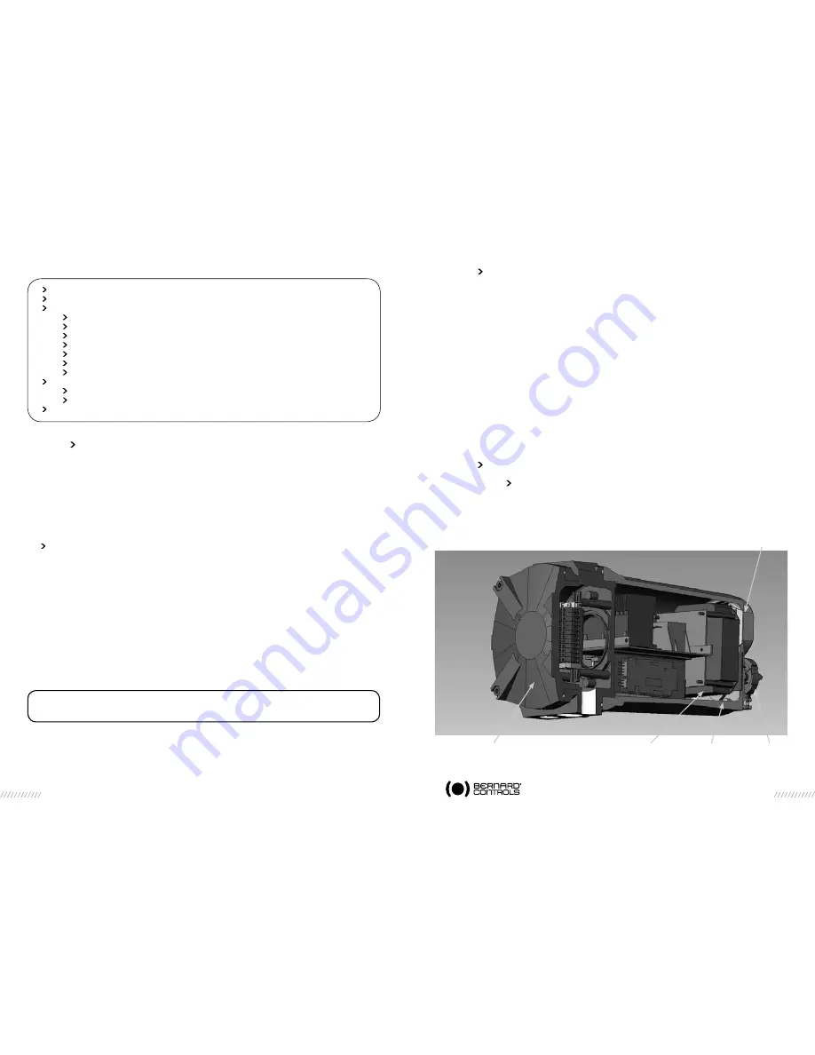
The Profibus module « Intellibus « located in the actuator is plugged on to the main board
and no access is needed.
fpX: explosion proof box
As far as actuators with I, or controls are concerned,
please refer to the Profibus DP for I instructions for start-up (NR1148).
Connection box
INTELLIBUS board
board
Button for
local control
Display


