6
INSTALLATION
7 UNPACKING THE PRODUCT
B
IDRA DS N
solar heaters are supplied in a single
package on a wooden pallet.
The insulation and the lining components of the models 750
and 1000 are supplied separately from the structural work
and are to be assembled upon receiving the product as
described in the paragraph "Assembly of the insulation and
the lining (models 750 - 1000)". For these models the mag-
nesium anode is supplied in a cardboard box.
The following items are delivered in a plastic bag inside the
packaging:
- Instruction manual
- Bar code label
- Hydraulic test certificate
- Energy label (to be applied to device upon installa-
tion)
- No. 4 adjustable feet to be mounted during installa-
tion (for models 750 - 1000 only).
b
The instruction manual is an integral part of the so-
lar storage cylinder. Once located, read it thoroughly
and keep it safe.
b
For handling operations, thoroughly follow the in-
structions on device package label.
8 ASSEMBLY OF THE INSULATION
AND THE LINING (MODELS 750 -
1000)
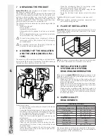
The assembly of the insulation and lining components must
be performed at the site of installation to facilitate passage
through any doors and/or entries to the room.
4
5
2
1
7
3
3
1
6
1
3
L
3
L
Proceed as follows:
- Fit the magnesium anode (6) with its seal in the sleeve
and fix it in place
- Assemble the insulating covers (1) around the body of
the heater, making sure that the engagement points
on the edges are positioned correctly. The edges are
not required to be closed completely
- Place the front protection plate (3) correctly on the
attachments
- Place the washers on the attachments and the pro-
tection for the inspection flange (4)
- Place the rear protection plate by closing the inter-
locking flaps (L) without closing completely (leave
one tooth open)
- Apply the upper insulation (2) and the upper cover
(5) (in order to insert the cover, exert a light and ho-
mogeneous pressure)
- Close the interlocking flaps (L) completely, which
were previously left with an open tooth
- Fit the cover of the inspection flange using the two
self-tapping screws (7) provided
- Apply the technical data plate and serial number
plate.
If disassembling is required, proceed in reverse order.
b
Wear suitable personal protective equipment and
use suitable safety devices.
9 PLACE OF INSTALLATION
B
IDRA DS N
solar heaters can be installed in all rooms
not requiring a level of electrical protection of the device
greater than IP X0D.
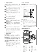
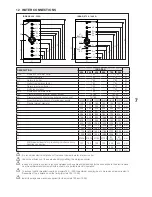
≥ 0,3 m
≥ 0,3 m
≥ 0,3 m
≥ 0,6 m
≥ 0,7 m
NOTE:
the above-indicated dimensions are recommended
for a correct maintenance and access to the device.
10 INSTALLATION IN OLDER
SYSTEMS AND SYSTEMS
REQUIRING MODERNISATION
When installing
B
IDRA DS N
storage cylinders in old
systems or systems requiring modernisation, always per-
form the following checks.
- Make sure that the system is fitted with safety and
control devices in accordance with applicable legis-
lation and standards
- Make sure that the central heating circuit has been
flushed out to remove all sludge and lime scale, and
has been vented and seal tested
- Make sure that a suitable water treatment system is
installed if the quality of the supply/recirculation water
so demands (refer to the reference values listed in
the table alongside).
11 WATER QUALITY
REQUIREMENTS
REFERENCE VALUES
pH
6-8
Electrical conductivity
less than 200 μS/cm (25°C)
Chlorine ions
less than 50 ppm
Sulphuric acid ions
less than 50 ppm
Total iron
less than 0.3 ppm
Alkalinity M
less than 50 ppm
Total hardness
less than 35°F
Sulphur ions
none
Ammonia ions
none
Silicon ions
less than 30 ppm
The values above ensure proper operation of the system.
Refer to the limit values specified in the current standards
and regulations on the installation site.
Installation


