ITALIANO
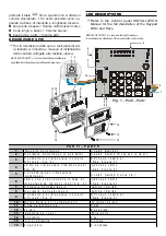
INSTALLAZIONE (FIG. 1)
Per l’installazione di questa Tastiera procedere
come descritto di seguito (vedere Figura 1)
1. Aprire lo sportello 14.
2. Svitare le viti 15.
3. Togliere il coperchio 16.
4. Togliere la Scheda Elettronica 11 dal fondo 12.
5. Se previsto, installare il Deviatore Antistrappo 2
come mostrato nel dettaglio ingrandito di Figura 1.
Il Deviatore Antistrappo è opzionale (art. ASNC).
Il Deviatore Antistrappo deve essere in-
stallato per ottenere la certificazione
IMQ-SISTEMI DI SICUREZZA al
II
LIvello
di Prestazione.
6. Passare il cavo per i collegamenti attraverso
l’apertura 13.
7. Fissare il Fondo 12 alla parete o alla scatola
predisposta tramite le opportune asole.
8. Se è stato installato il Deviatore Antistrappo 2,
fissare il Tassello Antistrappo 1.
ATTENZIONE - Il Deviatore Antistrappo è ineffica-
ce se la Tastiera viene fissata ad una scatola.
9. Riagganciare la Scheda Elettronica 11 al Fondo 12.
10. Se installato, collegare il cavetto del Deviatore
Antistrappo 2 al connettore 5.
11. Impostare il LIVELLO BPI come descritto nel
paragrafo omonimo.
12. Impostare l’INDIRIZZO come descritto nel pa-
ragrafo “Codifica dei Dispositivi”.
13. Eseguire i COLLEGAMENTI sulla morsettiera
10 (vedi fig. 2).
14. Riagganciare il Coperchio 16 al Fondo 12.
15. Avvitare le viti 15.
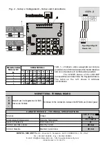
COLLEGAMENTI (FIG. 2)
T
ALISON/8L è utilizzabile nelle centrali Omnia4-
8 e Kyo4-8-32.
LIVELLO BPI (FIG.2)
Il Livello BPI della Tastiera deve essere uguale a quello
della centrale alla quale sarà collegata (leggere le istru-
zioni della centrale per conoscere il suo Livello BPI).
Il Livello BPI della Tastiera si imposta tramite i ponticelli 3
e 9 come mostrato nella Tabella di Figura 2.
®
M A D E
IN
ITA LY
ALISON/8L
Tastiera di Controllo a LED
LED Control Keypad
ENGLISH
INSTALLATION (FIG. 1)
Work carefully through the following steps (see
Figure 1).
1. Open the flip 14.
2. Remove the screws 15.
3. Remove the frontplate 16.
4. Detach the PCB 11 from the backplate 12.
5. Insert the Snatch Switch 2 as per Figure 1 (for
keypads with Snatch Switches only).
The Snatch Switch is an accessory item (order
code ASNC).
Keypads which are not fitted with Snatch
microswitches, DO NOT COMPLY with
IMQ-SECURITY SYSTEM Performance
level
II
certification.
6. Pull the connection wires through the wire entry
13.
7. Using wall anchors, secure the backplate 12 to
the wall or onto an outlet box.
8. Secure the Snatch bracket 1 to the wall (for
keypads with Snatch Switches only).
The Snatch Switch cannot be used when mount-
ing the ALISON/8L on an outlet box.
9. Reattach the PCB 11 to the backplate 12.
10. Connect the Snatch switch 2 to the connector
5 (for keypads with Snatch Switches).
11. Set the BPI Level, as described under
‘SETTING UP THE BPI LEVEL’.
12. Assign the Address, as described under
‘ASSIGNING THE ADDRESS’.
13. Complete the Connections on the terminal
board 10, refer to ‘CONNECTIONS’.
14. Replace the Frontplate 16.
15. Using the screws 15 secure the Frontplate.
CONNECTIONS (FIG. 2)
T
ALISON/8L is compatible with Omnia4-8 and
Kyo4-8-32 Control panels.
SETTING UP THE BPI LEVEL (FIG. 2)
The BPI Level of the keypad must match the BPI
Level of the Control panel (refer to your Control
panel manual for details).
Using jumpers 3 and 9, as per Table in Figure 2,
select the keypad BPI Level.


