

1
Wireless Slim Keypad
Model:
RW132KL1P; RW132KL2P
Installation Instructions
1 General Description
The Wireless Slim keypad is used to remotely operate the WiComm Smart
Hub. The two-way keypad receives a reply status indication from the Smart
Hub for each command that it sends.
You can use a proximity tag or enter a code to operate and use the functions
of the keypad.
2 Installation
Step 1: Mounting Considerations
Mount the keypad near the entrance of the house to easily arm and disarm
your security sysytem on a daily basis. In additon, place the keypad that
ensures good communciation between the keypad and Smart Hub.
Step 2: Quick Device Allocation
The keypad must identify itself to the WiComm Smart Hub. This can be
performed either using the RISCO Express Wizard
(www.riscocloud.com/express) by adding the keypad at the time of the
Smart Hub system installation or later either by using the “Settings” on the
Web (www.riscocloud.com) or using the WiComm Smart Hub, as follows:
1. Press the
button on the WiComm Smart Hub for 5 seconds; the unit
beeps once as it enters Learn mode (all the LEDs also light up, one after
the other).
2. Remove the red isolation strips to activate the batteries.
3. Send a signal transmission from the keypad by pressing
and
simultaneously for at least 2 seconds; the Smart Hub beeps once
to accept or beeps three times to reject. Once accepted, the system
announces the device.
The WiComm Smart Hub beeps once to accept or beeps three times
to reject. Once accepted, the system announces the device type and
its zone (for example, “Detector, zone 1”).
4. To complete allocation, momentarily press the WiComm Smart Hub
button
. A short beep is head and the LEDs stop flashing.
5. Mount the keypad
Note:
For future use, it is recommended to write down the keypad
description, zone number, and installation location of each allocated keypad.
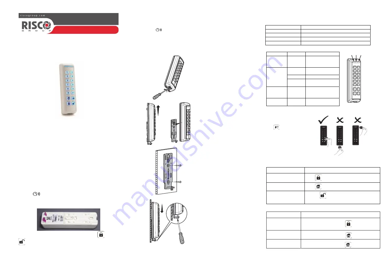
3 Installation
1. Remove the locking pin
securing the mounting
bracket to the unit.
2. Separate the mounting plate
from the keypad's main unit.
3. Mount the bracket to the wall
using the supplied screws.
4. Mount the keypad to the
bracket.
4 Buzzer and LED Indications
Buzzer Indications:
Duration Operation
Long beep
Confirmation
3 short beeps
Wrong code
Pulsed beeps
Exit/enty beeps (programmable)
Short beep
Each key press
LED Indciations:
Color
State
Status
Blue Blink
During
communcation with
the panel
Red
On
System fully or
partially armed
Slow flash During Exit delay
Rapid
flash
During alarm
Green
Blink
Trouble indication in
the system while the
system is unset
Green/Red
toggle
Toggle Waiting
for
code
to
be entered
5 Using the Proxmity Tag
The proximity tag, is
correctly used by applying it
within a 2 cm distance from
the
key
as shown in the
illustration (after waking the
keypad by pressing the
appropriate key).
6 Common Operations
Common Operations
Operation Action
Away arming
Press
Stay / Home arming
Press
Disarm
1. Press
> Code or present Proximity tag
(after wakeup)
Advanced Operations
Operation
Action
Partition 1/2/3 Arming
(Away)
Select partition 1/2/3 and press
Stay arm partition 1/2/3
Select partition 1/2/3 and press
Partition Disarm
Select partition 1/2/3 and press
followed by Code
1
Blue Red Green


