background image


17

4 Level 1 Cosmetic / Appearance / Alignment Service 

4.1 Software / Firmware Upgrade Process 

Upload firmware to MCU via VGA Cable 

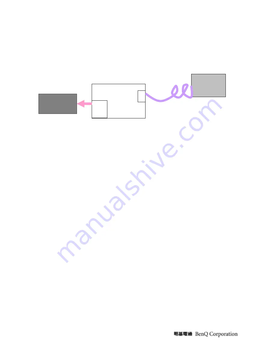
1. Connect ISP board between monitor and PC as below configuration.     


2. Press the “connect” button in ISP.exe, and select the device type, which is used in this monitor. Choose the 

corresponding firmware version, and load to MCU. 

3. After finish, please plug out power cable and re-start monitor again. 


4.2 Alignment Procedure (for function adjustment) 

4.2.1 Preparation: 

1. Setup input timing VESA to 1680*1050@60Hz,32-Grays pattern. 

2. Setup units and keep it warm up for at least 30 minutes. 


4.2.2 Timing adjustment 

1. Enter to factory mode setting area (by pressing “ENTER”+ “MENU” + “POWER” at the same time during power off). 

2. Check the settings to following values: 

 Contrast 

=50; 

 Brightness=90; 

 Color 

enhancement=general; 

3. Then turn off the monitor power. 


4.2.3 Function key Definitions   

4.2.3.1 Control buttons on the Back bezel 


        “MENU” 

„


When OSD displays, press [MENU] to return to previous level menuView the next 

function in the OSD Main menu 

„


When OSD isn’t shown on screen, press [MENU] to enter OSD interface 

„


Press [MENU] to enter Service Page When OSD isn’t shown on screen in Service Page 

Mode 


“ENTER” 

Insert to Parallel 

Port  on PC 

ISP Board 

LCD Monitor 

D-Sub 

Parallel 

Port


D-SUB 

Содержание G2010W

Страница 1: ...2008 5 8 Notice For RO to input specific Legal Requirement in specific NS regarding to responsibility and liability statements Please check BenQ s eSupport web site http esupport benq com to ensure th...

Страница 2: ...t Timings 8 3 7 Operational Function Specification 11 3 8 LCD Characteristics 13 3 9 User Controls 14 3 10 Mechanical Characteristics 14 3 11 Pallet Shipment 15 4 Level 1 Cosmetic Appearance Alignment...

Страница 3: ...diagnostics tests troubleshoot problems and align the BenQ product 1 1 Trademark The following terms are trademarks of BenQ Corporation BenQ Importance Only trained service personnel who are familiar...

Страница 4: ...ower cable immediately and consult your closed dealer z Always unplug the monitor before cleaning it Clean the cabinet with a clean dry cloth Apply non ammonia based cleaner onto the cloth not directl...

Страница 5: ...normal on operation 55W LED Green DMPS 2W LED Orange In rush Current 100Vac cold star 25 C 240Vac cold star 25 C 40A max 60A max To be determined by the business country Earth Leakage Current Hi pot P...

Страница 6: ...formance Item condition Spec OK NA Remark Max support Pixel rate 165MHz Max Resolution 1680 1050 Rise time Fall time 25 of minimum pixel clock period Refer to VESA VSIS Standard V1R2 Setting Time afte...

Страница 7: ...7 Vertical Sync polarity or 55 76Hz 3 5 Plug Play DDC2B DDC CI Support Item condition Spec OK NA Remark DDC channel type DDC 2B EDID Version 1 3...

Страница 8: ...56 25 36 00 Non preset 14 800 x 600 37 88 60 32 40 00 Preset 15 800 x 600 48 08 72 19 50 00 Non preset 16 800 x 600 46 88 75 00 49 50 Preset 17 800 x 600 53 67 85 00 56 25 fail safe mode 18 848 x 480...

Страница 9: ...768 47 78 59 87 79 50 Non preset 43 1280 x 768 60 29 74 89 102 25 Non preset 44 1280 x 768 68 63 84 84 117 50 fail safe mode 45 1280 x 800 61 648 59 81 83 50 Preset 46 1280 x 800 62 8 75 106 5 Preset...

Страница 10: ...25 fail safe mode 65 1600 x 1000 R 61 648 59 910 108 5 fail safe mode 66 1600 x 1200 75 00 60 00 162 00 fail safe mode 67 1600 x 1200 81 25 65 00 175 50 fail safe mode 68 1600 x 1200 87 50 70 00 189 0...

Страница 11: ...2 1920 X 1200 94 04 74 93 245 25 Out of range mode 83 1920 X 1200 107 18 84 93 281 25 Out of range mode 84 1920 X 1440 90 00 60 00 234 00 Out of range mode 85 1920 X1440 112 50 75 00 297 00 Out of ran...

Страница 12: ...g brightness max value 100 Min brightness value 3 7 3 Acoustical Noise Item condition Spec OK NA Remark Acoustical Noise At 1 meter distance audio function disable 3 7 4 Environment 3 7 5 Transportati...

Страница 13: ...Signal to noise ratio Output power 3 8 LCD Characteristics 3 8 1 The physical definition technology summary of LCD panel Item condition Spec OK NA Remark LCD panel supplier AUO Panel type of supplier...

Страница 14: ...e an adjustment value B When MENU OSD un displays press to Show Picture Mode Menu press to show Brightness Contrast Menu POWER Power on or power off the monitor iKey press iKey to perform auto adjustm...

Страница 15: ...Bezel painting 3 10 4 Carton 3 11 Pallet Shipment 3 11 1 Container Specification Stowing Type Containter Quantity of Produces sets Every container Quantity of Produces sets Every Pallet Quantity of Pa...

Страница 16: ...ion Product Net Weight Kg Gross Weight Kg Dimension w o Base LxWxH mm Dimension w Base LxWxH mm 4 07 0 5 Kg Net 5 12 0 5Kg 472 54X62 2X373 5mm 472 54X166 66X383 67mm Package Carton Interior Dimension...

Страница 17: ...pattern 2 Setup units and keep it warm up for at least 30 minutes 4 2 2 Timing adjustment 1 Enter to factory mode setting area by pressing ENTER MENU POWER at the same time during power off 2 Check th...

Страница 18: ...on off the monitor 4 2 3 2 OSD Control The On Screen Display OSD shall be an easy to use icon based menu through keypad OSD buttons or remote control unit The unit shall leave the factory with all OS...

Страница 19: ...Factory Mode Introduction When signal is input press power key to turn off the monitor Press ENTER MENU Power together to turn on the monitor After power on press MENU to call out Main Menu then pres...

Страница 20: ...or and color analyzer Modes switching check 1 Use Chroma Pattern Generator to make sequence VESA 640x480800x6001024x7681680x1050 and power saving signal etc 2 Confirm the above timing modes must be fu...

Страница 21: ...21 Power Key Off no...

Страница 22: ...22 5 Level 2 Disassembly Assembly Circuit Board Standard Parts Replacement 5 1 Exploded Diagram...

Страница 23: ...BLE COND 60x35xT0 07mm LEFT LE2016 1 ASSY BACK COVER 1 SCREW P CROSS M4 8 BLACK NL NYLOK 2 LE 20D6 LCD Monitor BEZEL 1 FUNCTION BUTTON 1 POWER BUTTON 1 LENS 1 PCBA KEY PAD 1 KEY PAD CABLE 1 ASSY BASE...

Страница 24: ...24 5 2 Assembly Block 1 Assemble the panel with front bezel 2 Assemble chassis Plug in the LVDS 3 Keypad assembly 4 Plug in the lamp lines...

Страница 25: ...25 5 Back cover assembly 6 Assemble the stand 7 Lock screw 8 Base assembly...

Страница 26: ...D6 LCD Monitor PANEL 1 HRN LVDS FFC 1 FOIL AI DOUBLE COND 60x35xT0 07mm LE2016 1 ASSY CHASSIS 1 BEZEL 1 FUNCTION BUTTON 1 POWER BUTTON 1 ASSY BASE BASE LE20D6 1 Rubber Foot 5 HRN ASS Y 1 PCBA I F BOAR...

Страница 27: ...27 2 Disassemble the stand take out screw 3 Move out the stand 4 Disassemble back cover 5 Move out LVDS 6 disassemble keypad...

Страница 28: ...28 7 Disassemble the LVDS 8 Take apart the chassis aside...

Страница 29: ...POWER SUPPLY 2008 01 08 InnoLux Document Number SIZE TITLE DATE SHEET OF Rev DRAWN BY CHECK BY APPRO BY C807 10u 25V C R A IC803 TLV431ALP R802 330K R806 150K R829 10K IC801 LTV817M 3 1 4 2 IC802 LD75...

Страница 30: ...30...

Страница 31: ...31...

Страница 32: ...70u 25V C523 10p 3KV R518 470K 1 R527 200 CN503 4100 D02 1 2 H L C505 1000p 50V D508 BAV99 1 2 3 R523 820 1 D506 BAT54 3 2 1 C525 470p 50V op2 C530 2200p 50V C504 1000p 50V R516 604K 1 5V C517 6800p 5...

Страница 33: ...the PWM signal then all the convert circuit go to a stable operating station R809 R810 R811 R812 is the brownout circuit to pin1 of IC802 Only the input AC voltage over the threshold level approximat...

Страница 34: ...output 8 bit even LVDS digital data to panel control circuit through CN103 U106 RTD2545LH 29 38 output 8 bit odd LVDS digital data to panel control circuit through CN103 U108 RTD2120_LQFP48 44 output...

Страница 35: ...oltage on pin8 of IC501 No Is Ok R501 Check I F board Yes R501 open No Yes Is there instantaneously pulse wave on pin1 pin3 pin15 of IC501 at the No Is Ok IC501 Yes U501 U502 fail No IC501 fail Yes Is...

Страница 36: ...ectifier voltage Check IC802 C805 T801 Check circuit if short Check F801 P801 D801 Check pin3 of IC802 voltage about 1V Check R801 R805 R822 R823 R817 Check pin2 of IC802 voltage about 2V Check R803 R...

Страница 37: ...t Check Vpin3 4 of IC801 about 6V Check Vpin1 2 of IC801 about Check C815 D806 R812 Check R809 R814 END Output Voltage Unstable Check Vbe of Q801 below Check circuit if short Check ZD801 ZD802 ZD803 C...

Страница 38: ...age of IC803 Check R809 R808 R814 Check D806 C815 if short Change Check pin1 of IC802 voltage Check pin3 of IC802 voltage Change R801 R805 R822 R823 R817 END Check the C pin voltage of IC803 Change Un...

Страница 39: ...in1 2 of CN101 Of U108 Check Crystal of U108 Check CCFL Enable of U108 MCU Fail Check X101 Inverter Fail OK NG OK OK NG Check Reset Of U108 Check pin5 of CN101 Check R102 R103 R106 Q103 Check C164 OK...

Страница 40: ...ange LVDS Cable Check VLCD Is 5V Check Panel Enable Of U108 is High Check R107 R109 R110 Q101 Q104 END Workmanship LVDS Cable NG Panel Fail Check LVDS Signals Check the HW Reset Of U108 Check the pins...

Страница 41: ...Cable Reinsert Change LVDS Cable Check the communication of the U108 and U105 Check the Pins of The U108 and U105 END Workmanship LVDS Cable NG Check RTD_SCLK RTD_SD3 SDI Reset NG NG NG OK OK OK Chec...

Отзывы: