


09/ 2013
BENNING MM 2
14
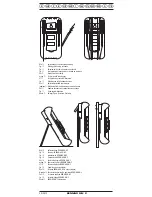
BENNING MM 2.
- Connect the red safety test lead to the input terminal for V, Ω,
,
of the
BENNING MM 2.
- Connect the safety test leads across the diodes and read the measured
value on the digital display
of the BENNING MM 2.
- For a typical silicone diode tested in the forward-biased direction a voltage
flow between 0,500 V and 0,900 V is displayed. A display showing "000"
indicates a short circuit in the diode, whereas a display showing "1" indi-
cates an open circuit in the diode.
- For a diode tested in the reverse-biased direction the display reads "1". If
the diode is damaged, the display will show "000" or other values.
see Figure 7:
Diode Testing
8.5 Continuity Testing with Buzzer
- Turn the rotary switch
of the BENNING MM 2 to select the appropriate
range identified by a buzzer and diode symbol.
-
Connect the black safety test lead to the COM-terminal
of the
BENNING MM 2.
- Connect the red safety test lead to the input terminal for V, Ω,
,
of the
BENNING MM 2.
- Connect the safety test leads to the circuit to be measured. If the circuit
resistance between the COM-terminal
and the input terminal for V, Ω,
,
falls below 50 Ω, then the built-in buzzer in the BENNING MM 2
emits a continuous tone.
see Figure 8:
Continuity Testing with buzzer
9. Maintenance
Remove test leads and turn the power off before opening the
BENNING MM 2! Dangerous voltage!
Any work to be carried out on an opened BENNING MM 2 under voltage
is
strictly reserved for qualified electrotechnical personnel who must take
special precautionary measures to avoid accidents.
This is how to ensure that the BENNING MM 2 is free from any voltage before
the instrument is opened:
- first remove the safety test leads from measured object.
- then remove both safety test leads from the BENNING MM 2.
- turn the rotary switch
to the "OFF" position.
9.1 Instrument safe-guarding
In certain circumstances, safety during the use of the BENNING MM 2 can no
longer be guaranteed; when for instance:
- there is visible damage to the housing
- measurement errors occur
- the instrument has been subjected to prolonged storage under unfavorable
conditions and
- the instrument has been subjected to severe transport stresses.
In such cases the BENNING MM 2 must be immediately switched off, removed
from the measurement points and secured against any future unintentional
operation.
9.2 Cleaning
Wipe the case of the BENNING MM 2 with a clean dry cloth (exception: spe-
cial cleaning cloths). Do not use any solvents and/ or abrasives to clean the
BENNING MM 2.
9.3 Battery replacement
Remove test leads and turn the power off before opening the
BENNING MM 2! Dangerous voltage!
The BENNING MM 2 is powered by a 9 V block battery. Battery replacement
(see figure 9 below) becomes necessary when the low battery indicator shows
in the display
.
This is how to change the battery:
- Remove the safety test leads from the measured circuit.
- Remove the safety test leads from the BENNING MM 2.
- Turn the rotary switch
to the "OFF" position.
- Remove the protective rubber holster
from the BENNING MM 2.
- Place the BENNING MM 2 on its front side and remove the three screws
from the case back.


