background image

WARNiNg

•  Before installing the automatic system read the instructions 

hereunder carefully.

•  It is strictly forbidden to use the product VN.S for applications 

other than indicated in this instruction handbook.

•  Show the user how to use the automation system.
•  Give the user the part of the leaflet which contains the instructions 

for users.

•  All Benincá products are covered by an insurance policy for any 

possible damages to objects and persons caused by construc-
tion faults, under condition that the entire system be marked CE 
and only Benincá parts be used.

OPERATiNg LiMiTS AND WARNiNgS

This geared motor has been studied and manufactured to activate 
balanced sectional doors (VN.S20/VN.ST20) as well as rolling doors 
(VN.S40/VN.ST40).
Before proceeding to install the system, make sure that the door 
is balanced and slides well. Check that the ropes, the springs and 
the parachuting system are in good conditions. For doors that have 
not been installed recently, check also all the other parts subject to 
wear and tear. The above instructions are essential for the safety 
of the system and the reliability of the operator.

iNSTALLATiON

Thanks to its versatility, this geared motor can be assembled not 
only on the right-side or left-side of the door, but also horizontally 
(fig. 2) or vertically (fig. 3). The geared motor has been designed 
to directly activate the cable winding shaft of the door which must 
feature 1” diameter (25.4mm) and should be provided of housing 
for the key. For cable winding shafts having a different diameter, 
an adapter should be provided (item VN.A30 for diam. 30 shafts, 
item VN.A3175 for diam. 31.75 shafts, item VN.A40 for diam. 40 
shafts). To fit the unit proceed as follows (fig.4):

• 

Check that the distance between the rope coiler shaft “A” and 
the surface onto which brackets should be fitted ranges between 
82 and 150mm.

•  Weld or fit the bracket “S” to surface with screws.
•  Introduce the gear motor in the rope coiler shaft, while interposing 

the key “C”.

•  Tighten the fitting screws “V”.
•  To mount the plate on side “B”, use screws TE M10x20 sup

-

plied.

To calculate the movement speed of the door, proceed as fol-
lows:

V = d (diam. of cable winding drum - m) x 3.14 x 24 = m/1’

It is possible to use the geared motor by extending the motion to 
the rope winding-up shaft by means of a chain (item VN.RM). The 
motion can possibly be transmitted reduced or multiplied (item 
VN.RV) (fig. 5).
To calculate the movement speed of the door, proceed as fol-
lows:

V = d (diam. of cable winding drum - m) x 3.14 x 24 x Z1 / Z2 = m/1’

WiRiNg (fig. 6)

VN.ST20 / VN.ST40

VN.S20 / VN.S40

GND

Earth.

Earth.

Not used.

Not used.

SWO

Open limit switch 1x0.5 min.

Open limit switch 1x0.5 min.

SWC

Close limit switch 1x0.5 min.

Close limit switch 1x0.5 min.

COM AUX

Common of the contact at disposal Common of the contact at disposal

Not used.

Not used.

AUX

3A, 24Vdc/ac max.

3A, 24Vdc max.

L1/M

L1

Phase

L2/COM

L2

Com.

L3/M

L3

Phase

Not used.

Not used.

COM SW

Common of Limit switch 1x0.5 min. Common of Limit switch 1x0.5 min.

---

Not used.

Not used.

VN.S20/VN.S40:

 The 25µF capacitor must be connected to the 

motor terminals 7 and 8 of THINK control unit.

To use the micro-switch supplied as a safety limit switch in the 
closing phase, modify the cable positions as per fig. 7.

N.B.:

 Models 400V three-phase can be used also at 230V three-

phase by changing from a star connection to a triangle one as per 
fig. 8.

ADjuSTMENT OF THE LiMiT SWiTCHES

The geared motor is equipped with 4 microswitches:

Red limit switch

Opening limit switch (SWO)

Blue limit switch

Opening over-travel (SWO XT)

Yellow limit switch

Closing limit switch (SWC)

Black limit switch

At disposal of the accessories (AUX)

To adjust the cams proceed as follows:

• 

Manually move the door until it is almost closed and adjust the 
SWC cam until the micro-switch is almost triggered (Fig. 9).

•  Tighten the dowel shown in Figure 10 by using a 2.5mm socket 

head key. 

•  By using the same key, carry out the micrometric adjustment of 

the cam, as shown in Figure 11.

•  Repeat the operation while opening the door and adjust the SWO 

cam.

•  Then position the SWO XT cam so that it is activated slightly 

delayed with respect to the SWO cam.

•  Power the automatic unit and operate it (if it is a closing operation, 

invert wires 1 and 3 of the motor power supply, fig. 6 and 7).

• 

Should  further  adjustments  be  required,  turn  the  micrometric 
adjustment dowel.

Figure 12 shows the wire diagram of limit switches in single-phase 
motors, while Figure 13 shown wire connections in three-phase 
motors.

Technical data

VN.S20

VN.ST20

VN.S40

VN.ST40

Power supply

Consumption

Power

Torque

* Door max. weight

Exit shaft hole

Max. force on Ø 120

Exit rounds

** L.S. reduction ratio

Jogging

Thermal switch trig.

Operat. temperature

Capacitor

Lubrication

Weight

Dimensions: see fig.1

1x230V (50Hz)

3A

600W

90Nm

3700N

25.4mm

1500N

24rpm

1/20

40%

130°C

-20°C / +70°C

20µF

Agip Blasia 32

15kg

3x400V (50Hz)

1.7A

800W

105Nm

4800N

25.4mm

1750N

24rpm

1/20

50%

130°C

-20°C / +70°C

Agip Blasia 32

15kg

1x230V (50Hz)

3A

600W

90Nm

3700N

25.4mm

1500N

24rpm

1/40

40%

130°C

-20°C / +70°C

20µF

Agip Blasia 32

15kg

3x400V (50Hz)

1.7A

800W

105Nm

4800N

25.4mm

1750N

24rpm

1/40

50%

130°C

-20°C / +70°C

Agip Blasia 32

15kg

* For balancing doors and diameter Ø 120mm of the steel cable winding drum.
** Max. no. of rounds from the exit shaft.

12

Содержание VN.S20

Страница 1: ...VN S20 VN S40 VN ST20 VN ST40 UNIONE NAZIONALE COSTRUTTORI AUTOMATISMI PER CANCELLI PORTE SERRANDE ED AFFINI L8542212 11 2010 rev11 ...

Страница 2: ......

Страница 3: ...00 190 5 251 70 100 361 211 248 120 Ø 25 4 27 8 6 4 100 190 5 251 70 100 361 211 248 120 Ø 25 4 27 8 1 2 352 5 288 120 68 16 22 263 150 max 82 min 150 max 263 288 Soffitto Ceiling Decke Plafond Techo Sufit 3 ...

Страница 4: ...3 4 S C V B A 288 120 68 14 6 16 15 140 110 15 22 Ø 11 263 150 max 352 5 82 min Parete Wall Wand Cloison Pared Ściana 4 ...

Страница 5: ...C 3 F C 4 4x1 5 min L1 M L2 COM L3 M COM SW GND SWO SWC COM AUX AUX a b c d e f g h i l m n o GND SWO SWC COM AUX AUX L1 L2 L3 COM SW GND SWO SWC COM AUX AUX M COM M COM SW VN MT VN M Non utilizzato Not used Nicht verwendet Non utilisé No utilizado Nie używany ...

Страница 6: ...czenie trójkątowe na 230V trójfazowy Centro stella Star centre Sternmitte Centre étoile Centro estrella Punkt wspólny w połączeniu gwiazdowym 6 7 Blu Blue Blau Bleu Azul Niebieski Giallo Yellow Gelb Jaune Amarillo Żółty Arancio Orange Orange Orange Naranja Pomarańczowy Viola Violet Violett Violet Violeta Fioletowy Non utilizzato Not used Nicht verwendet Non utilisé No utilizado Nie używany Rosso N...

Страница 7: ...9 10 11 7 ...

Страница 8: ...low Black Violet SAFETY SWITCH Red Blue Yellow Black AUX SWC SWO SWO SWC AUX COM SW COM AUX SWO XT Red Brown Brown White White Blue SWO SWO SWO XT Red Brown White Blue Orange Yellow Black Violet SAFETY SWITCH Black Black CIRCUIT BREAKER Red Blue Yellow Black 8 ...

Страница 9: ... impianto di messa a terra rispondente alle vigenti norme di sicurezza Durante gli interventi di installazione manutenzione e ri parazione togliere l alimentazione prima di accedere alle parti elettriche Le descrizioni e le illustrazioni presenti in questo manuale non sono impegnative Lasciando inalterate le caratte ristiche essenziali del prodotto il fabbricante si riserva il diritto di apportare...

Страница 10: ...1x0 5 min Finecorsa apre 1x0 5 min SWC Finecorsa chiude 1x0 5 min Finecorsa chiude 1x0 5 min COMAUX Comune del contatto a disposizione Comune del contatto a disposizione Non utilizzato Non utilizzato AUX 3A 24Vdc ac max 3A 24Vdc max L1 M L1 Fase L2 COM L2 Com L3 M L3 Fase Non utilizzato Non utilizzato COMSW Comune finecorsa 1x0 5 min Comune finecorsa 1x0 5 min Non utilizzato Non utilizzato VN S20 ...

Страница 11: ... that the gate connection be earthed During installation maintenance and repair cut off power supply before accessing to live parts Descriptions and figures in this manual are not binding While leaving the essential characteristics of the product unchanged the manufacturer reserves the right to modify the same under the technical design or commercial point of view without necessarily update this m...

Страница 12: ...VN ST20 VN ST40 VN S20 VN S40 GND Earth Earth Not used Not used SWO Open limit switch 1x0 5 min Open limit switch 1x0 5 min SWC Close limit switch 1x0 5 min Close limit switch 1x0 5 min COMAUX Common of the contact at disposal Common of the contact at disposal Not used Not used AUX 3A 24Vdc ac max 3A 24Vdc max L1 M L1 Phase L2 COM L2 Com L3 M L3 Phase Not used Not used COMSW Common of Limit switch...

Страница 13: ...typologien verlangen den Anschluss des Flügels an eine Erdungsanlage laut den geltenden Sicherheitsnormen Während der Installation der Wartung und der Reparatur die Anlage stromlos machen bevor an den elektrischen Teilen gearbeitet wird Die in diesem Handbuch enthaltenen Beschreibungen und Abbildungen sind nicht verbindlich Ausgenommen der Haupteigenschaften des Produkts behält sich der Hersteller...

Страница 14: ...endet SWO Fernschalter öffnet 1x0 5 min Fernschalter öffnet 1x0 5 min SWC Fernschalter schliesst 1x0 5 min Fernschalter schliesst 1x0 5 min COMAUX Gemeinsamer Leiter des entsprechenden Kontaktes Gemeinsamer Leiter des entsprechenden Kontaktes Nicht verwendet Nicht verwendet AUX 3A 24Vdc ac max 3A 24Vdc max L1 M L1 Phase L2 COM L2 Com L3 M L3 Phase Nicht verwendet Nicht verwendet COMSW Gemeinsamer ...

Страница 15: ... une protection de sur courant adéquats Certains types d installation requièrent le branchement du vantail à une installation de mise à terre satisfaisant les normes de sécurité e vigueur Avant toute intervention d installation réparation et main tien couper l alimentation avant d accéder aux parties électriques Les descriptions et les illustrations présentées dans ce manuel ne sont pas contraigna...

Страница 16: ...x 3 14 x 24 x Z1 Z2 mètres 1 Câblages fig 6 VN ST20 VN ST40 VN S20 VN S40 GND Mise à la terre Mise à la terre Non utilisé Non utilisé SWO F C ouvre 1x0 5 min F C ouvre 1x0 5 min SWC F C ferme 1x0 5 min F C ferme 1x0 5 min COMAUX Commun du contact disponible Commun du contact disponible Non utilisé Non utilisé AUX 3A 24Vdc ac max 3A 24Vdc max L1 M L1 Phase L2 COM L2 Com L3 M L3 Phase Non utilisé No...

Страница 17: ...que se conecte la hoja con una instalación de puesta a tierra conforme a las vigentes normas de seguridad Durante las operaciones de instalación mantenimiento y reparación cortar la alimentación antes de acceder a las partes eléctricas Las descripciones y las ilustraciones presentadas en este manual no son vinculantes Sin cambiar las características esenciales del producto el fabricante se reserva...

Страница 18: ...C abre 1x0 5 min F C abre 1x0 5 min SWC F C cierra 1x0 5 min F C cierra 1x0 5 min COMAUX Común del contacto a disposición Común del contacto a disposición No utilizado No utilizado AUX 3A 24Vdc ac max 3A 24Vdc max L1 M L1 Fase L2 COM L2 Com L3 M L3 Fase No utilizado No utilizado COMSW Común del F C 1x0 5 min Común del F C 1x0 5 min No utilizado No utilizado VN S20 VN S40 Conectar el condensador de...

Страница 19: ...tóre typologie instalacji wymagają podłączenia skrzydła do uziemienia zgodnego z obowiązującymi nor mami bezpieczeństwa Podczas prac instalacyjnych konserwacji i naprawy przed przystąpieniem do prac na częściach elektrycznych należy odciąć zasilanie Opisy i ilustracje znajdujące się w niniejszym podręczniku podane są wyłącznie przykładowo Pozostawiając niez mienione istotne charakterystyki technic...

Страница 20: ...a mech otwierania 1x0 5 min SWC Krańcówka mech zamykania 1x0 5 min Krańcówka mech zamykania 1x0 5 min COMAUX Wspólny styku do dyspozycji Wspólny styku do dyspozycji Nie używany Nie używany AUX 3A 24Vdc ac max 3A 24Vdc max L1 M L1 Faza L2 COM L2 Com L3 M L3 Faza Nie używany Nie używany COMSW Wspólny Krańcówka Wspólny Krańcówka Nie używany Nie używany VN S20 VN S40 Kondensator 25µF musi być zmostkow...

Страница 21: ...ove the door in case of power failure or failure of the system pull the release cord fig 14 It is important that the door is well balanced To reset the automatic mode pull the other cord When the unit is powered again if it doesn t work check that the L lever is in the correct position as a safety microswitch automatically releases the motor during the manual operation If the operator overtravels ...

Страница 22: ...ños jueguen con los mando o en proximidad de la puerta En caso de anomalías de funcionamiento no intentar reparar la avería sino que avisar a un técnico especializado Maniobra manual y de emergencia Para desplazar la puerta en caso de corte de energía eléctrica o de avería tirar del cordel de desbloqueo fig 14 Es importante que la puerta esté bien balanceada Para restablecer la operación automátic...

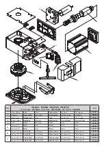
Страница 23: ...chtel Boîtiers câbl Caja cableados Skrzynka okabl 9686855 5 Carter Cover Abdeckung Carter Tapa Karter 9686856 A Motore VN S Motor Motor Moteur Motor Silnik 9686857 Motore VN ST Motor Motor Moteur Motor Silnik 9686858 B Alb cam VN 40 Cam shaft Nockenwelle Arbre à cames Eje excéntricas Wałek krzywek 9686859 Alb cam VN 20 Cam shaft Nockenwelle Arbre à cames Eje excéntricas Wałek krzywek 9686860 C Alb...

Страница 24: ...AUTOMATISMI BENINCÀ SpA Via Capitello 45 36066 Sandrigo VI Tel 0444 751030 r a Fax 0444 759728 ...

Отзывы: