


89000109-002
xVue Touch Installation Manual
Rev 2
Page 4-4
© Honeywell International Inc. Do not copy without express permission of Honeywell.
For Use in Non-Certified Aircraft
(2) Insert pinned wires into J1 connector housing per Table 5-1 KSD 100EXP J1 Pin Descriptions
(3) Insert the J1 connector housing into the backshell base and secure with the two captive socket
head jack post screws.
(4) Insert the tiedown strap in the backshell base and secure the wire bundle.
(5) Install the backshell cover to the backshell base with the two countersunk screws. Torque screws
to 4 ± 0.4 in-lbs (0.45 ± 0.05 Nm).
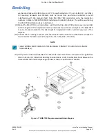
(6) Secure each cable harness shield ground to the J1 backshell assembly with the button head
ground screws and lock washers, see Figure 4-8 Bottom Side of J2 Backshell. Torque screws to 4 ±
0.4 in-lbs (0.45 ± 0.05 Nm).
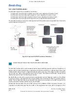
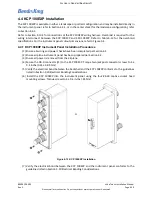
4.3.1.2 J2 Connector/Configuration Module Assembly
The KSD 100 J2 Connector/Configuration Module Assembly mounts to the lower D-Sub receptacle (P2)
located on the back of the KSD 100EXP. The Configuration Module CCA is installed in the backshell
assembly of the J2 connector.
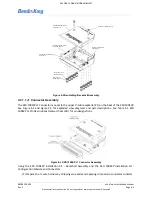
See Figure 4-2 BendixKing Backshell Assembly, Figure 4-4 KSD 100EXP J2 Connector Assembly, and Figure
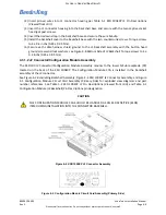
4-5 Configuration Module Circuit Card Assembly (Primary Side) for exploded view diagrams and part
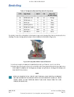
number references. See Table 5-2 KSD 100EXP J2 Pin Descriptions (Viewed from LRU) and Table 4-1
Configuration Module (J2 Backshell) Pin Descriptions pin designation.
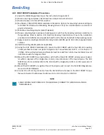
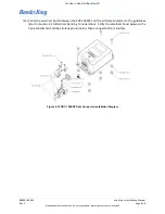
Figure 4-4 KSD 100EXP J2 Connector Assembly
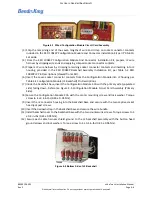
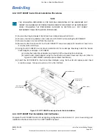
Figure 4-5 Configuration Module Circuit Card Assembly (Primary Side)
CAUTION
THE CONFIGURATION MODULE CCA SHOULD BE HANDLED AS AN ESD SENSITIVE (ESDS)
ITEM DURING INSTALLATION INTO THE CONNECTOR BACKSHELL.


