background image

2

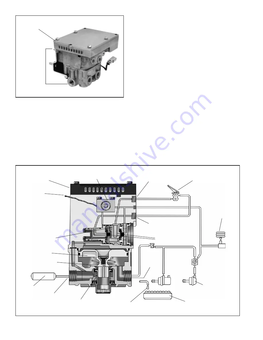
ATR-1DC

ANTILOCK
TRACTION

RELAY
VALVE

EC-16

 CONTROLLER

FIGURE 2 - TYPICAL AT-1DC

 ANTILOCK TRACTION ASSY.

FIGURE 3 - SECTIONAL AT-1DC

 ANTILOCK TRACTION ASSEMBLY

The ATR-1DC

 valve is part of the R-12

 family of relay valves

which includes the R-12

, R-14

, BP-R1

, AR-1

& ATR-1

valves.  The internal components of the relay portion of all of
these valves are similar and in many cases interchangeable
with the R-12

 valve and therefore the same basic

components are used to service all of them.  The ATR-1DC

valve is available with various crack pressures to
accommodate specific applications, however the standard
is 4 psi, achieved without any added spring.

OPERATION

GENERAL

While the ATR-1DC

 valve is an antilock-traction relay valve

its true function is that of an air brake relay valve.  Because
the ATR-1DC

 is essentially a relay valve, with a traction

control function, the following description of operation
describes its operation as a relay valve and its function in
the traction control system.  The full operation of the
antilock system and separate antilock components and their
operation is not addressed in this publication.  For a
description of antilock operation, refer to the appropriate
Service Data Sheet covering the electronic controller used
with the ATR-1DC

 valve (e.g. SD-13-4785 for the EC-16

electronic controller, or SD-13-4788 for the EC-17

 electronic

controller).  Other useful information on antilock system
components may be downloaded from www.bendix.com. For
example: SD-13-4793 (M-21

 and M-22

 antilock

modulators), SD-13-4870 (M-32

 and M-32QR

 antilock

modulators), SD-13-4754 (WS-20

 wheel speed sensors),

and SD-13-4860 (WS-24

 wheel speed sensors).

SERVICE BRAKES - APPLYING

Reservoir air pressure is present at the supply port (SUP)
and at the relay inlet and exhaust valve.  Reservoir air
pressure also flows from the supply port through internal

TRACTION CONTROL SOLENOID

SUPPLY PORT

SECONDARY

SERVICE PORT

DOUBLE

CHECK VALVES

DELIVERY

PORT

EXHAUST PORT

RELAY PISTON

INLET-EXHAUST

VALVE

BLEND BACK

PISTON

SOLENOID

CONNECTOR

BRAKE VALVE

(SHOWING

DELIVERY AIR

LINES ONLY)

AIR BAG

BRAKE

CHAMBER

TONE RING

EC-16

 OR EC-17

CONTROLLER

WHEEL SPEED

SENSOR

PRIMARY

SERVICE PORT

RELAY PISTON

SPRING

(IF USED)

RESERVOIR

Содержание ATR1DC ANTILOCK TRACTION RELAY

Страница 1: ...a cover plate can be installed and the antilock controller mounted elsewhere on the vehicle When an ATR 1DC valve is combined with an antilock traction controller the resulting assembly is referred to as a antilock traction assembly or AT 1DC TheATR 1DC valve replaces the standard relay valve used to control the rear axle service brakes and performs the standard relay function Like the standard re...

Страница 2: ... of the antilock system and separate antilock components and their operation is not addressed in this publication For a description of antilock operation refer to the appropriate Service Data Sheet covering the electronic controller used with the ATR 1DC valve e g SD 13 4785 for the EC 16 electronic controller or SD 13 4788 for the EC 17 electronic controller Other useful information on antilock s...

Страница 3: ...nse to primary control and seals the air passage leading to the secondary control Air flows past double check valve diaphragm B and through a passage in the cover to the top of the service relay piston In response TRACTION CONTROL SOLENOID SUPPLY PORT SECONDARY SERVICE PORT DOUBLE CHECK VALVE A DELIVERY PORT EXHAUST PORT RELAY PISTON INLET EXHAUST VALVE BLEND BACK PISTON SOLENOID CONNECTOR AIR BAG...

Страница 4: ...re above and below the relay piston is equal the piston moves FIGURE 7 SERVICE BRAKES APPLYING PRIMARY CIRCUIT DELIVERY FAILED TRACTION CONTROL SOLENOID SUPPLY PORT SECONDARY SERVICE PORT DOUBLE CHECK VALVE A DELIVERY PORT EXHAUST PORT RELAY PISTON INLET EXHAUST VALVE BLEND BACK PISTON SOLENOID CONNECTOR AIR BAG BRAKE CHAMBER TONE RING EC 16 OR EC 17 CONTROLLER WHEEL SPEED SENSOR PRIMARY SERVICE P...

Страница 5: ... control port and primary delivery circuit of the brake valve Air flows past double check valve diaphragm B and through a passage in the cover to the top of the service relay piston In response to air pressure the relay piston drain valve flexes and seals the drain passage leading to the relay exhaust Simultaneously the relay piston moves into contact with the exhaust portion of its inlet and exha...

Страница 6: ... AT 1DC ANTILOCK TRACTION ASSY EC 16 OR EC 17 CONTROLLER ATR 1DC VALVE MODULATOR MODULATOR REAR AXLE BRAKE REAR AXLE BRAKE EXCITER SPEED SENSOR EXCITER SPEED SENSOR MODULATOR BRAKE CHAMBER ENGINE CONTROL MODULE ECM TRACTION SWITCH ANTILOCK DASH LAMP TRACTION DASH LAMP RETARDER SWITCH MODULATOR ...

Страница 7: ...lve s exhaust port PREVENTIVE MAINTENANCE GENERAL Perform the tests and inspections presented at the prescribed intervals If theATR 1DC valve fails to function as described or leakage is excessive it should be repaired or replaced with a new or genuine Bendix remanufactured unit available at any authorized parts outlet EVERY 3 MONTHS 25 000 MILES OR 900 OPERATING HOURS 1 Remove any accumulated con...

Страница 8: ...8 FIGURE 10 ATR 1DC ANTILOCK TRACTION ASSEMBLY EXPLODED VIEW 4 3 5 6 7 8 9 10 11 18 19 21 20 24 23 22 26 25 27 28 29 30 31 15 14 13 17 2 1 16 32 33 38 12 39 34 35 36 37 40 13 ...

Страница 9: ...ery port pressure from the 10 psi service pressure to obtain the differential Compare the measured differential with the pressure specified for theATR 1DC valve part number see the l D washer also for the differential NOTE For ATR 1DC valves not incorporating a relay piston return spring 20 the measured differential should be approximately 4 psi When a spring is in use the differential will be hig...

Страница 10: ...lve seat 23 with o rings 27 28 Remove o rings 27 28 from the check valve seat 12 Remove the check valve 24 guide 25 and spring 26 13 Remove the inlet seat 29 with o rings 30 31 then remove o rings 30 31 from the inlet sea 29 14 Remove the check valve seat 32 from the valve cover 3 Remove both o ring 33 15 Remove the check valve 34 guide 35 and spring 36 16 Remove the primary inlet seat 37 with o r...

Страница 11: ...9 in the body 4 12 Install the large and small diameter o rings 7 8 in the exhaust cover 6 then install the exhaust cover in the body 4 taking care not to damage the o rings Hold the exhaust cover in place 13 While depressing the exhaust cover 6 install the retaining ring 5 in the body 4 Make certain the retainer 5 is fully seated in its groove in the body 14 If the valve was equipped with a relay...

Страница 12: ...12 BW1969 2004 Bendix Commercial Vehicle Systems LLC All rights reserved 9 2004 Printed in U S A ...

Отзывы: