


iso685-D-B_D00177_05_M_XXEN/07.2017
26
Display
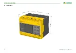
8. Display
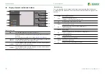
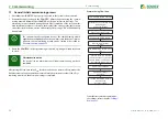
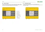
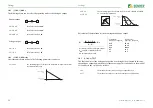
8.1 Standard display
During normal operation, the ISOMETER® displays the message OK and below, the
currently measured insulation resistance.
In the bottom line of the display, the set limit values for R(an) are indicated.
In the example below,
R
an1
=40 kΩ and
R
an2
=10 kΩ.
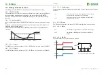
The signal quality of the measurement suits the selected profile.
The better the signal quality, the faster and more exact the device can
measure.
The signal quality of the measurement does not suit the selected pro-
file. Select a different measurement profile.
Update period between the test pulses
IT
System
O K
2 3 0
kΩ
R(an) 40kΩ/10kΩ
O K
2 3 0
kΩ
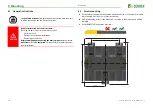
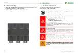
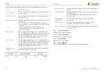
8.2 Fault display (active)
An active fault is displayed by
. The upper part of the display will become orange and
displays the fault message.
Depending on the type of fault, the LEDs ALARM 1, ALARM 2 or SERVICE are activated.
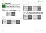
In the example below, the insulation resistance is still 7 kΩ. Since the values
R
an1
=40 kΩ
and
R
an2
=10 kΩ are both below the set response value, ALARM 1 and ALARM 2 have been
triggered.
If several fault messages have appeared, you can navigate through the faults using the
and button.
If the value falls below
R
an1
in a DC system or a DC shift is recognised in an AC system,
additional detailed information regarding the DC shift will be displayed, as illustrated
above.
7 kΩ
Insulation fault
7
kΩ
1/4


