


Connection
Connection
iso685-D-B_D00177_05_M_XXEN/07.2017
18
Provide line protection!
According to DIN VDE 0100-430, a line protection shall be provided for the
supply voltage.
Risk of injury from sharp-edged terminals!
Risk of lacerations.
Touch the enclosure and the terminals with due care.
Ensure disconnection from the IT system!
When insulation or voltage tests are to be carried out, the device must be
isolated from the system for the test period. Otherwise the device may be
damaged.
Risk of property damage due to unprofessional installation!
If more than one insulation monitoring device is connected to a conduc-
tively connected system, the system can be damaged. If several devices
are connected, the device does not function and does not signal insula-
tion faults. Make sure that only
one
insulation monitoring device is con-
nected in each conductively connected system.
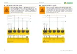
The ISOMETER® iso685-D-B is suitable for use in coupled systems. For the
necessary parameter setting, refer to
“Special functions for coupled IT sys-
Risk of property damage due to unprofessional installation!
The connecting lines L1/+, L2, L3/- to the system to be monitored must be
carried out as spur lines. Inadmissible load current can result in damage
to property and personal injury. Do not apply any load current to the ter-
minals.
Check proper connection!
Prior to commissioning of the installation, check that the device has been
properly connected and check the device functions. Perform a functional
test using an earth fault via a suitable resistance.
CAUTION
CAUTION
CAUTION
CAUTION
CAUTION
Prevent measurement errors!
When an AC system being monitored contains galvanically coupled DC
circuits, take into consideration that: an insulation fault can only be de-
tected correctly when the rectifier valves carry a minimum current of
>10 mA.
For UL applications:
Use 60/70 °C copper lines only!
For UL and CSA applications, the supply voltage must be protected via 5 A
fuses.


