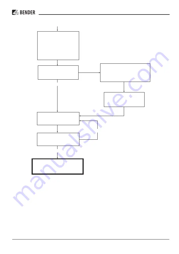
Commissioning of the ISOMETER® (3)
IR1575H_D00416_00_M_XXEN / 03.2021 13
ISOMETER® IR1575H
Страница 1: ...ISOMETER IR1575H Insulation monitoring device for IT AC and DC systems Software version D0275 V1 3 Manual EN IR1575H_D00416_00_M_XXEN 03 2021 ...
Страница 2: ...3 cents 30 sec remaining time 6 3 cents min Mobile phone higher depending on mobile phone tariff Repair service Repair calibration and replacement service Londorfer Strasse 65 35305 Grünberg Germany Telephone 49 6401 807 780 technical issues or 49 6401 807 784 785 commercial issues Fax 49 6401 807 789 E mail repair bender service de Field service On site service Telephone 49 6401 807 752 762 techn...
Страница 3: ...hart 11 4 Connection 14 5 Operation and setting 15 5 1 Diplay and operating elements 15 5 1 1 Display in standard mode 15 5 1 2 Display in menu mode 15 5 1 3 Function keys 16 5 2 Menu structure and menu mode 17 5 3 Menu ISO SETUP Setting of the ISOMETER functions 19 5 3 1 Response values Alarm1 and Alarm2 19 5 3 2 Operating principle 19 5 3 3 Memory setting on off 20 5 4 PASSWORD menu 21 5 5 LANGU...
Страница 4: ...4 IR1575H_D00416_00_M_XXEN 03 2021 ...
Страница 5: ... comply with the information in the operating instructions regarding transport commissioning operation and maintenance of the ISOMETER Unauthorized structural modifications to the ISOMETER Failure to comply with the technical data Improperly executed repairs and the use of spare parts or accessories which are not re commended by the manufacturer Cases of disaster and force majeure Assembly and ins...
Страница 6: ...ase inform the Bender company immediately The devices must only be stored in areas protected from dust damp and spray or dripping water and in which the specified storage temperatures are maintai ned 1 2 4 Note Make sure that the operating voltage is correct Prior to insulation and voltage tests the ISOMETER must be disconnected from the power system for the duration of these tests In order to che...
Страница 7: ...isconnected from the protective conductor PE In order to check the proper connection of the device it is recommended to carry out a functional test using a genuine insulation fault RF e g via a suitable resistance The device variant 4 is delivered with the following factory setting ISO SETUP Alarm 1 Alarm 2 40 kΩ 10 kΩ ISO SETUP Operating mode K1 K2 N O operation ISO SETUP Memory off Please check ...
Страница 8: ...n a non volatile memory EEPROM The IR1575H superimposes a microprocessor controlled pulsating AC measuring voltage on the system being monitored AMP measuring principle The adaptive measuring pulse is a measu ring method developed and patented by Bender European Patent EP 0 654 673 B1 The measuring pulse consists of positive and negative cycles of the same amplitude The period depends on the respe...
Страница 9: ...al measuring mode and the currently measured value will be displayed once the measuring time has elapsed When a device or connection fault is found the message Error appears on the display the system fault LED lights the relay K2 21 22 24 switches and the corresponding fault message see table will be indicated If such a system fault occurs another self test will be started after approximately one ...
Страница 10: ...out by pressing the buttons RESET MENU and TEST sequentially Proceed as follows 1 Press and hold down the RESET button 2 Press and hold down the MENU button 3 Press the TEST button for at least two seconds After these steps are run through the run control and the self test will be started again 10 IR1575H_D00416_00_M_XXEN 03 2021 Function ...
Страница 11: ... three page commissioning flow chart the encircled numbers correspond to the numbers in the legend to wiring diagram see page 14 to Commissioning 2 technical data A0 A1 or A0 A2 H H IR1575H_D00416_00_M_XXEN 03 2021 11 ISOMETER IR1575H ...
Страница 12: ...Commissioning of the ISOMETER 2 to Commissioning 3 12 IR1575H_D00416_00_M_XXEN 03 2021 Commissioning flow chart ...
Страница 13: ...Commissioning of the ISOMETER 3 IR1575H_D00416_00_M_XXEN 03 2021 13 ISOMETER IR1575H ...
Страница 14: ... reset inputs for collective ISOMETER testing is not allowed Wiring diagram Legend 1 Supply voltage Us see nameplate technical data on page 24 or ordering information via 6 A fuse 2 3 Connection to the 3AC system being monitored Connect the terminals L1 L2 to neutral conductor N or terminals L1 L2 to conductor L1 L2 4 Connection to the DC systems being monitored Connect terminal L1 to conductor L ...
Страница 15: ...firm parameter change 5 ALARM LED 1 lights insulation fault first warning level reached 6 ALARM LED 2 lights Insulation fault second warning level reached or system fault alarm 1 Indication of the insulation resistance in kΩ 2 Additional information about the insulation resistance Insulation fault at L Insulation fault at L s A new measuring process has been started 3 Polarity of the test current ...
Страница 16: ...ss the MENU key to call up the menu system Use the Arrow UP and Arrow DOWN keys and the ENTER key to scroll through the menu system UP key To move up in the menu to increase the parameter value DOWN key To move down in the menu to decrease the parameter value Enter key To select a menu item or submenu item To confirm or save a parameter change and return to the associated submenu item or skip to t...
Страница 17: ...y you have to enter the valid password before changing the parameters by means of the UP DOWN keys Once the password is entered correctly all parameters can be changed as long as you stay in the menu Changing the parameters usually has an immediate effect on the measuring and alarm functions The changed parameter is stored in a non volatile memory after returning to the submenu by pressing the ENT...
Страница 18: ...Diagram menu structure 18 IR1575H_D00416_00_M_XXEN 03 2021 Operation and setting ...
Страница 19: ...e alarm relay is deenergized during normal operation K1 N C N C operation contacts 11 12 14 without relay test the alarm relay is energized during normal operation K1 N O N O operation contacts 11 12 14 without relay test the alarm relay is deenergized during normal operation K1 Flash flashing function contacts 11 12 14 the alarm relay switches and the LED flashes in the event of an alarm message ...
Страница 20: ...ally be activated as system fault relays 5 3 3 Memory setting on off Memory on Fault memory is activated The device must be reset with the RESET button after clearing the fault Memory off Fault memory deactivated factory setting 1 Exit 100 200 N O N O off N O Test N C Test Flash N O N C on off 2 1 1 EXIT 2 ISO SETUP 20 IR1575H_D00416_00_M_XXEN 03 2021 Operation and setting ...
Страница 21: ...ettings and modifications Use the arrow keys to select the desired password menu item 2 password xxx and confirm with ENTER to finish the action Select the menu item 3 Status on with the ENTER key By default the password is deactivated 3 Status off PASSWORD diagram IR1575H_D00416_00_M_XXEN 03 2021 21 ISOMETER IR1575H ...
Страница 22: ...t the language for the fault messages You have the choice between German and English All the device menus are displayed in English irrespective of the selected language Language diagram 22 IR1575H_D00416_00_M_XXEN 03 2021 Operation and setting ...
Страница 23: ...us settings It is intended to provide fast fault clearance by qualified experts in the event of a device error 5 7 INFO menu Use this menu to query the type of the respective device In addition the software version used in the device appears on the display INFO diagram IR1575H_D00416_00_M_XXEN 03 2021 23 ISOMETER IR1575H ...
Страница 24: ... at A0 A1 see also device nameplate DC 10 2 84 V IR1575H Power consumption 5 VA Response values Response value Ran1 Alarm1 2 kΩ 1 MΩ Response value Ran2 Alarm2 2 kΩ 1 MΩ Relative percentage error 2 kΩ 10 kΩ 2 kΩ Relative percentage error 10 kΩ 1 MΩ 0 20 Response time tan at RF 0 5 x Ran and Ce 1 µF 5 s Measuring time see characteristic curves Hysteresis 2 kΩ 10 kΩ 2 kΩ Hysteresis 10 kΩ 1 MΩ 25 Mea...
Страница 25: ... g 10 150 Hz Ambient temperature during operation 10 C 55 C Storage temperature range 40 C 70 C Climatic class acc to IEC 60721 3 3 3K23 Operating mode continuous operation Mounting display oriented Connection plug in screw terminals Connection rigid flexible 0 2 4 mm2 0 2 2 5 mm2 Connection flexible with connector sleeve without with plastic sleeve 0 25 2 5 mm2 Conductor sizes AWG 24 12 Degree of...
Страница 26: ...itances Ce 1 100 µF Un 0 793 V 50 Hz 6 4 Ordering information Type Nominal voltage Un Supply voltage Us Art No IR1575H 435 3 N AC 0 793V AC 0 793V DC 0 575V AC 88 264V AC 340 460V DC 77 286V B91064005 Label for modified versions There will only be a label in this field if the ISOMETER is different from the standard version 1 10 100 1000 1 10 100 Ce μ μF 10 MΩ Ω 0 kΩ Ω RF tan s 26 IR1575H_D00416_00...
Страница 27: ...6 5 Dimension diagram enclosure IR1575H designed for panel mounting The required knock outs are illustrated in the figure below IR1575H_D00416_00_M_XXEN 03 2021 27 ISOMETER IR1575H ...
Страница 28: ...r de www bender de All rights reserved Reprinting and duplicating only with permission of the publisher Bender GmbH Co KG PO Box 1161 35301 Grünberg Germany Londorfer Str 65 35305 Grünberg Germany Tel 49 6401 807 0 Fax 49 6401 807 259 E Mail info bender de www bender de IR1575H_D00416_00_M_XXEN 03 2021 pdf Bender GmbH Co KG Germany Subject to change The specified standards take into account the ed...