


16
5. Commissioning and continous operation
5.1 Specific factory settings
5.2 Functional test before first use
1. Check the correct mechanical mounting of the VG12 to the power generator.
2. Make sure that the connecting cable of the VG12 is connected to the generator secu-
rely.
3. Ensure that other socket-outlets of the generator are sealed.
4. Start the power generator.
5. Plug a load (e.g. an AC 230 V hand lamp) into a socket-outlet of the VG12 safety distri-
butor. The lamp should light up.
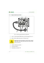
6. Press the
combined
test/reset button "T/R" of the VG12. A short time later, "tES"
appears on the display for a few seconds.
In the following, the alarm LEDs "AL1" and "AL2" light up and the VG12 disconnects all
poles of the safety socket-outlets (The hand lamp goes out).
The specific factory settings of the ISOMETER® IR123 in the VG12 differ
from the standard factory settings of an IR123!
Response value 1/2 (Alarm 1/2):
Operating mode K1/K2:
Fault memory:
Start-up delay:
Response delay:
Password:
46 kΩ/23 kΩ
N/C operation (n.c.)
activated (on)
t = 0 s
t
on
= 0 s
0, deactivated
CAUTION
Risk of malfunction!
If the power generator is
not
switched off after pressing the combined
test/reset button "T/R", a fault exists. Protect the power generator
against accidental switch-on. Please contact Bender.