


System description
10
3.3.1 Display and operating elements
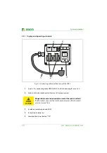
Fig. 3.1: Connecting cable and front view of the VG12
1
Input: 0.7 m connecting cable H07RN-F3G 2.5 with Schuko plug for max. 16 A
2
Output: 2 Schuko socket-outlets for max. 16 A output current
CAUTION
Danger due to excessive nominal current at the socket-outlets!
If both sockets are used, the total nominal current of both sockets
must not exceed 16 A.
3
Insulation monitoring device IR423
4
Instruction for daily test
5
Combined test/reset button "T/R"
Achtung!
Tägliche Prüfung
Kombinierte Test/Reset-Taste:
- lang drücken (> 2 s) = TEST
"AL1" und "AL2" leuchten
- kurz drücken (< 1,5 s) = RESET
"AL1" und "AL2" erlöschen
Bedienungsanleitung beachten!
Attention!
Daily test
Combined test/reset button:
- long pressing (> 2 s) = TEST
"AL1" and "AL2" light
- short pressing (< 1.5 s) = RESET
"AL1" and "AL2" go out
Refer to operating manual!
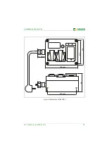
1
2
3
4
"T/R"
5