background image

 TGH1402en/11.2020 15

MF loop monitor

Time behaviour

Start-up delay 

t

  ....................................................................................................................................................  1…10 s (1 s)*

Response delay 

t

on2

 (Alarm)  ..............................................................................................................................  0.1…1 s (0,2 s)*

Response delay 

t

on1

 (pre-warning)  ....................................................................................................................  0.1…1 s (0,2 s)*

Delay on release 

t

off

 ...............................................................................................................................................  1…10 s (1 s)*

Operating time 

t

ae

   ........................................................................................................................................................ ≤ 100 ms

Response time 

t

an

  ................................................................................................................................................. 

t

an

 = 

t

ae

 + 

t

on1/2

Cable lengths for measuring current transformers

Single wire ≥ 0.75 mm

2

  .................................................................................................................................................  0…1 m

Single wire, twisted ≥ 0.75 mm

2

  .................................................................................................................................  0…10 m

Shielded cable ≥ 0.5 mm

2

  ............................................................................................................................................  0…40 m

Recommended conductor 

(shielded, shield one-end at terminal l of SRCM420 and not earthed)
 ......................................................................................................................................................................J-Y(ST)Y min. 2 x 0.8
Connection  .........................................................................................................................................................  screw terminals

Displays, memory

Display range measuring value  ................................................................................................................................ 2…250 mA
Operating uncertainty  .................................................................................................................................  0…-30 %/± 2 digit
Password  ......................................................................................................................................................... off/0…999 (off)*

Inputs/outputs

Cable length for external TEST/RESET button  ...............................................................................................................  0…10 m

Switching elements

Switching elements  ............................................................................................. 2 x 1 changeover contact, 11-12-14, 21,22, 24
Operating principle  ................................................................................................................................................  N/C operation
Electrical endurance/number of cycles  .............................................................................................................................. 10 000

Contact data acc. to IEC 60947-5-1

Utilisation category  ................................................................................................. AC-13…AC-14…DC-12…DC-12…DC-12
Rated operational voltage  ............................................................................................ 230 V…230 V…24 V…110 V…220 V
Rated operational current  .......................................................................................................  5 A…3 A…1 A…0.2 A…0.2 A
Minimum contact rating ............................................................................................................................ 1 mA at AC/DC ≥ 10 V

Environment/EMC

EMC  ............................................................................................................................................................... IEC 62020: 2003-11
Operating temperature  .....................................................................................................................................  -25 ºC…+55 ºC

Classification of climatic conditions acc. to IEC 60721

Stationary use (IEC 60721-3-3) .......................................................................  3K23 (except condensation and formation of ice)
Transport (IEC 60721-3-2)  ..............................................................................  2K11 (except condensation and formation of ice)
Long-term storage (IEC 60721-3-1)  ...............................................................  1K22 (except condensation and formation of ice)

Classification of mechanical conditions acc. to IEC 60721

Stationary use (IEC 60721-3-3) ...........................................................................................................................................  3M11
Transport (IEC 60721-3-2)  ....................................................................................................................................................  2M4
Long-term storage (IEC 60721-3-1)  ...................................................................................................................................  1M12

Содержание AF460

Страница 1: ...402en 11 2020 MF loop monitor System for monitoring the trailing cable protective earth conductor by a measurement frequency loop Suitable for mobile electrical equipment in non gassy underground and...

Страница 2: ...0 sec remaining time 6 3 cents min Mobile phone higher depending on mobile phone tariff Repair service Repair calibration and replacement service Londorfer Strasse 65 35305 Gr nberg Germany Telephone...

Страница 3: ...6 Disposal of Bender devices 6 1 7 Safety 6 2 MF loop for monitoring the PE conductor 7 2 1 Intended use 7 2 2 Function 7 3 Installation and connection 10 3 1 Required components 10 3 2 Installation...

Страница 4: ...4 TGH1402en 11 2020...

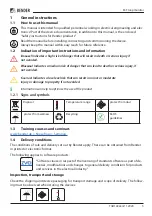
Страница 5: ...w level risk that can result in minor or moderate injury or damage to property if not avoided i Information can help to optimise the use of the product 1 2 1 Signs and symbols Disposal Temperature ran...

Страница 6: ...operating manual and the enclosed safety instructions must be observed by all persons working with the device Furthermore the rules and regulations that apply for accident preven tion at the place of...

Страница 7: ...d the frequency se lective SRCM420 residual current monitor As soon as the current drops below the response value an alarm is output and the contactor BS shuts down 2 2 2 Components of the MF loop mon...

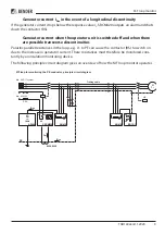
Страница 8: ...closes the MF conductor loop This increases the generator current IGen to 50 60 mA The SRCM420 detects a current outside the alarm range and terminates the alarm output In other words the LEDs AL1 an...

Страница 9: ...r current when the operator unit is switched off and when there are possible transverse discontinuities Parasitic parallel resistances in the loop e g L1 to PE can cause the contactor BS to switch on...

Страница 10: ...SRCM420 must be snapped into position on DIN rails inside the switch cabi net 2 The measuring current transformer must be installed near the earthing point of the PE conductor It can be installed usin...

Страница 11: ...TGH1402en 11 2020 11 MF loop monitor The MF loop monitor is run on 3 phase AC IT systems with a maximum nominal voltage Un of 1000 V Connect the components according to the connection diagram...

Страница 12: ...erator current IGen T Test button 1 5 s starts a self test Up button 1 5 s displays the response values R Reset button no function Down button 1 5 s displays the response values MENU MENU key for menu...

Страница 13: ...Insulation coordination acc to IEC 60664 1 IEC 60664 3 Rated voltage 250 V Rated impulse voltage degree of pollution 4 kV III Protective separation reinforced insulation between A1 A2 AK1 AK2 PE Outp...

Страница 14: ...1 5 Frequency selective current monitor SRCM420 Factory setting Insulation coordination acc to IEC 60664 1 IEC 60664 3 Rated voltage 250 V Rated impulse voltage degree of pollution 4 kV III Protective...

Страница 15: ...n 0 10 m Switching elements Switching elements 2 x 1 changeover contact 11 12 14 21 22 24 Operating principle N C operation Electrical endurance number of cycles 10 000 Contact data acc to IEC 60947 5...

Страница 16: ...0 5 0 6 Nm Other Operating mode continuous operation Position of normal use any Degree of protection built in components DIN EN 60529 IP30 Degree of protection terminals DIN EN 60529 IP20 Enclosure ma...

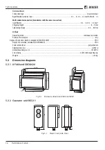
Страница 17: ...itor 5 2 3 Coupling device AG410 Fig 5 1 Views Side Front 5 2 4 Measuring current transformers W20 and W35 Transformer type A mm B mm C mm W20 mounting with 2 angles diagonal 47 21 4 63 W35 mounting w...

Страница 18: ...AG410 3 phase AC 50 60 Hz 0 1000V B97022022 BG12 1 DC 19 2 26 4V B97022023 SRCM420 D 2 DC AC 42 460 Hz 70 300V 30 100 mA 1 kHz B97022020 Absolute values for the voltage range External measuring curre...

Страница 19: ...password Connection monitoring The connections to the measuring current transformer are constantly monitored If there is an er ror the alarm relays K1 K2 trip without delay and the LEDs AL1 AL2 ON fl...

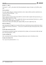
Страница 20: ...delay of the device tae and de lays the output of the signal total delay tan tae ton If the error no longer exists during the response delay the alarm signal drops out Delay on release toff After the...

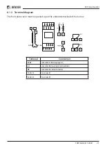
Страница 21: ...t plate cover must be opened up on the underside marked with an arrow Terminal Connection A1 A2 Connection to the voltage supply Us k l Connection for measuring current transformer T R Connection for...

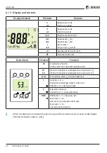
Страница 22: ...rror or fault in the connection monitor AL1 AL2 LED Alarm 1 lit up yellow value dropped below response value 1 I1 LED Alarm 2 lit up yellow value dropped below response value 2 I2 53 mA 53 mA generato...

Страница 23: ...eter AL Response values I2 I2 Alarm 2 I1 I1 Alarm 1 Hys Hysteresis I2 I1 t Time controller t on 1 Response delay K1 t on 2 Response delay K2 t Start up delay t off Delay on release K1 K2 SEt Device co...

Страница 24: ...ws 1 Press the MENU Enter button for longer than 1 5 s The abbreviation AL flashes on the display 2 Confirm with Enter The parameter I1 flashes 3 Press the Down button in order to choose the parameter...

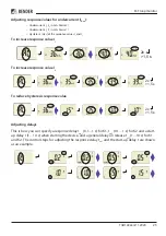
Страница 25: ...ase response value I1 To increase response value I2 To reduce hysteresis response value Adjusting delays This is how you can specify a response delay ton1 0 1 1 s for K1 ton2 0 1 1 s for K2 and a star...

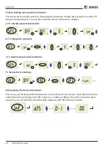
Страница 26: ...settings a To activate password protection b To change the password c To deactivate password protection To restore factory settings Interrogating the device information This is how you interrogate the...

Страница 27: ...onse value I2 35 mA Response value I1 36 mA Hysteresis 15 Mode of operation K1 N C operation n c Mode of operation K2 N C operation n c Response delay K1 ton1 0 2 s Response delay K2 ton2 0 2 s Start...

Страница 28: ...bender de www bender de All rights reserved Reprinting and duplicating only with permission of the publisher Bender GmbH Co KG PO Box 1161 35301 Gr nberg Germany Londorfer Str 65 35305 Gr nberg Germa...

Отзывы: