Benassi BL30 Скачать руководство пользователя страница 6


SpA


BL 30 / 35 


6

• 

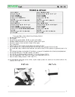
In the model BL35 pulling the reverse gear lever between the internal sides of the belt should be 25-35 mm (PICT 14). 

• 

In the model BL 35 H with forward gear lever engaged you should keep the distance of about 55 mm between the internal sides of 
the belt (see picture 15). If the rear clutch is engaged, the distance between both internal sides of the belt should be of about 40 
mm, as you can check in picture 15/1. If the distance is different, you should adjust the tension of the idlers by means of the register 
screws “L” and “M” of picture 16, so that the belts do not s lide when the idlers are tightened. If this adjustment is still not enough, 
you can move the engine on its guides after having turned out the clamping bolts: move the engine towards the handlebar if you 
have to reduce the space, or viceversa. 

• 

The standard  handlebars can be adjusted unscrewing the knob “N” (PICT 17) and setting the screw in one of the tree holes and 
than locking it again with the knob. 

• 

In the type with full side and vertical adjustment (PICT 18) you have to release the blocking lever “P” than adjust the handlebar 
position as you prefer and lock it again. 

• 

The standard tiller is 57 cm wide, with two sets of knives on each side, and the side protection plates. 

• 

Adding other two sets of blades you can extend the tiller to 80 cm (PICT 6). The blades of the tiller- knives should always be directed 
ahead, towards the front of the machine. 

• 

We recommend to use the tiller with the side plates because they improve the stability of the machine and they protect from plants 
and any other obstacle. 

• 

As optional accessory the machine can fit an adjustable ridger delivered complete with its own support which should be fitted on the 
rear side of the machine, replacing the standard spur.  


          - PICT n°12-                                 -PICT n°13-   


-PICT. n°14- 


-PICT n°15-                              -PICT n°15/1-  


      -PICT n°16- 


                -PICT17-                               -PICT 18-  


TILLER


Содержание BL30

Страница 1: ...Spa USE AND MAINTENANCE CULTIVATOR MODEL BL30 BL35 3035 1 11 25 11 2002...

Страница 2: ...certainly get satisfactory performances for a long time Please read very carefully this booklet before using your cultivator The greater attention you give to our technical instructions the more reli...

Страница 3: ...BL30K BL35K provided with oil filter ENGINE LUBRICATION WITH see instruction manual of the engine Quantity of engine oil see instruction manual of the engine Fuel white petrol Safety device for both...

Страница 4: ...r screws and nuts The protection guards should reach a width of 60 cm according to the CE PICT n 7 SECURITY TERMS WARNING Please read very carefully this booklet before using your cultivator Carefully...

Страница 5: ...U SHOULD FILL IT UP TO THE LEVEL ON THE DIP STICK OF THE OIL CUP Please check the engine USE AND MAINTENANCE concerning the operations before staring Start the engine only in open spaces 1 Pull the ch...

Страница 6: ...standard handlebars can be adjusted unscrewing the knob N PICT 17 and setting the screw in one of the tree holes and than locking it again with the knob In the type with full side and vertical adjustm...

Страница 7: ...TMENT The pin fixing the big pulley has also a safety purpose in case heavy obstacle it will break avoiding damages to other parts of the machine The replacement of the pin is very easy you have to in...

Страница 8: ...9 THE PRESIDENT S Matteo della Decima 25 11 2002 TEST AND RESULT TYPE CULTIVATOR MODEL BL30 T Measured acoustic power Lwa 92Db Guaranteed acoustic power Lwa 95dB 2000 14 CE EN ISO 3744 ISO 11094 Vibra...

Отзывы: