background image

Содержание QSK100AX

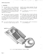
Страница 1: ... Sets 1 02 These sets are significantly different in that the dials are located in the handset RECALL BUTTON 1 03 The QSK100AX has a rotary dial while the QSK2100AX contains a Touch Tone Dial 1 04 Use H3QA Handset for manual service See Fig 11 for handset connections 1 05 This section is reissued to make minor re visions and add connection information for 3A Speakerphone System Fig 1 Desk Mounted ...

Страница 2: ...holes of the fingerwheel to be reduced resulting in a more compact dial 2 03 A 3 Conductor Mounting Cord is provided with the set Other mounting cords if required may be ordered separately The code of the cord varies with the service to be provided See Para 3 03 2 04 The QSK2100AX Touch Tone version is shown in Fig 1A 2 05 When these sets are used as a desk set the handset when in place rests in t...

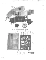
Страница 3: ...rty flat rate service R v E Ring party flat rate service A D Use with 1A1 and 1A2 Key Sy tems Not to be used for Tip Party A N The telephone set is available in the fol lowing colours 3 02 WARM WHITE 20 3 03 DEEP TURQUOISE MAUVE BRIGHT RED PALE YELLOW DEEP BLUE IVORY GREEN BEIGE Identification of Par ts See Table A 21 22 23 24 25 50 51 60 Fig 2 Parts Handset Assembly QSK100AX Page 3 ...

Страница 4: ...SECTION S02 321 910CA Page 4 Fig 2A Parts Handset Assembly QSK2100AX Fig 3 Parts Base Assembly 1 ...

Страница 5: ... GASKET TRANSMITTER GASKET RECEIVER CARD HOLDER WINDOW RECEIVER BRACKET 5 6 CORD CORD NOTE 1 CORD NOTE 2 ASSEMBLY DIAL Includes Transmitter Cup REMARKS FIG 3 FIG 2 FIG 2A FIG 2 FIG 3 FIG 2 FIG 1 FIG 2 FIG 1 FIG 2 FIG 3 FIG 2A NOTE 1 D4QC cords are available in 5 ft 6 in and 13 ft lengths and will be ordered as required for 1A1 Key Systems or when individual or 2 Party installation includes 13 ft c...

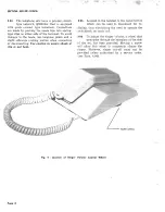
Страница 6: ...Use caution to assure shank of clip is not bent I 3 05 Located in the handset is the recall button which can be used to disconnect for re dialing thus eliminating the need to operate the switchhook on each call 3 06 To adjust the ringer volume a wheel that protrudes through the baseplate at the side of the set has been provided Moving a screw will allow this wheel to completely silence the ringer ...

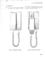
Страница 7: ...la tion shall be as covered in Sections Fig 5A Wall Mounted On Hook ISS Of SECTION 502 321 910CA 502 120 200 and 502 120 201 respectively How ever as the set is a combined desk wall telephone additional information is provided Fig 58 Wall Mounted Off Hook Page 7 ...

Страница 8: ... grommet See Fig 7 Press the handle of the tool towards the grommet and push the shank into the slot as far as it will go Push the handle of the release tool away from the grommet to release the returning spring and gently ease the grommet out of the handset shelL NS16750 LIST 2 RELEASER RETAINING SPRING GROMMET Fig 7 Removal of Handset Grommet c Once the grommet has been withdrawn two screws are ...

Страница 9: ...ing can be uncovered for the wire entry by removing the handset cord grommet from the base rotating it 1800 and replacing it 4 04 To provide the ringer cut off f eat u l e autho rized by service order change the position of the lever associated with the ringer volume control wheel With housing of the base off remove the screw that holds the lever in contact with the wheel shift the lever to the op...

Страница 10: ...nes on which dialing is to be restricted This will shunt pulsing con tacts on these lines Page 10 5 MAINTENANCE 5 01 Normal maintenance will involve replace ment of the following parts See Para 3 03 for identification of parts DIAL QSK100AX Only CORDS TRANSMITTER RECEIVER FEET SWITCHHOOK See Caution Note TRANSMITTER CUP QSK100AX only ASSEMBLY DIAL includes Transmitter cup QSK2100AX Only Caution Ho...

Страница 11: ...replace the complete dial as replacement in the field may result in permanent damage to the dial The finger wheel need not be removed for number tag insertion 5 07 Disc Centre Dial Insert the NS16750 L2 releaser in the small hole adjac ent to the number 5 hole and pry disc off 5 08 Ringer Open base see Para 4 02 Loosen screw in volume control and re move ringer mounting screws Replace ringer 5 09 ...

Страница 12: ...SECTION 502 321 910CA Page 12 Fig 9 Slitting Sheath Fig 10 Cutting Sheath ...

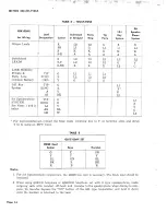
Страница 13: ...2 Party Line RING R L2 L2 Ll Common Battery GRD Y G G G lAl Key TIP G Ll System RING R C A Y G Al BK L2 3A Speakerphone TIP G Ll SYSTEM RING R C See Notes 1 and 2 Al Y Y below Table E AG BL G LK W L2 For wall mounted sets connect the Ring red incoming line to Y on terminal strip and strap Y to C of network using an MlW Cord For wall mounted sets connect the Ring red incoming line to X on terminal ...

Страница 14: ... RING R X See Notes land 2 Al Y Y below AG BL G LK W L2 For wall mounted set connect the Ring red incoming line to Y on terminal strip and strap Y to X using an MlW Cord TABLE E QSK2100AX SET H5QE Cord Colour Base Handset G X GN Y C Y BL GN BL BK R BK R B R Notes 1 For 3A Speakerphone connections the D6QB line cord is necessary The black lead should be insulated 2 When using QSKIOO telephone or QS...

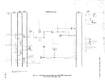
Страница 15: ...RR a S BR I m DIQA SWITCH TERM INAL RINGER HOOK f MTG STRIP COILS CORD r t r I I I W iiiil i I I iii I i L1 i TIP GJm 0 m S G I e I w I d Wi SLoW m BK f J i 0 W i i o i l 0 W GND s _ K X I za I 0 R RING R I l ii J 111 EARLY MODELS MAY HAVE R LEAD CONNECTED TO L3 Q co CD UI Fig 11 Schematic for Individual Line QSK100AX Rotary Dial See Table B for other uses UI o to I Co to 0 ...

Страница 16: ...CORD TERMINAL ASSY QNB18A CORD D3Q5A STRIP d 1 RCVR G L1 S G s w TIP BK C RR x m m L OGI oJ a C L s S K BL GN W F R r 0 Y G t 0 GND S R Wi t r GN A L L3 R B RECALL 0 S BR l R S Y r I RING I l BK Y F U r L C U Y 0 w I 0 0 ca lD o ca lD 0 EARLY MODELS MAY HAVE R LEAD CONNECTED TO L3 Fig 12 QSK 2100 AX Touch Tone Bridged Individual I T ...

Отзывы: