

.,
a
ca
CD
-o
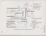
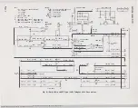
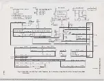
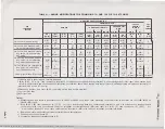
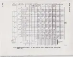
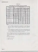
TABLE A- WIRING MODIFICATIONS FOR COMBINING lA AND IAI OR IA2 KTS LINES
MOUNTING CORD LEADS (NOTE 1)
CHAINING SWITCH
TEL SET
SET
KEY
30-BUTTON SETS
CONTROL
LINE
TELEPHONE
HOLD KEY
18· AN
0
30-BUTTON SETS
ONLY
(NOTE 2)
SWITCH
SYSTEM
1ST KEY
2ND KEY
3RO KEY
4TH KEY
5TH KEY
RING
A1
(Y·G)
(G-Y)
(V-0)
(BR-V)
(V-BR)
(V·G)
(V-G)
(V-G)
(V-G)
(V·G)
(BL·V)
(O·Y)
(BR)
[BK-BL]
[BK-W]
[s.w]
[s.Y]
[S-BK]
[BL-W]
[BL·W)
[BL·W)
[BL-W]
(BL-W)
[R]
[Y]
[S·G)
A-H
A-H
.
.
.
A-H
A-H
A-H
A-H
A-H
R
lB
lAl or 1A2 (shop wiring)
(I)
(I)
(I)
(II)
(III)
(IV)
(V)
(I)
(Note 4)
t
lAl or 1A2 on first key unit;
A-H
y
.
It
R
(Y)
A-H
A-H
A-H
A-H
R
lB
t
lA on remaining key units
(I)
(Note 4)
(I)
(II)
(Note 4)
(II)
(
I
II)
(IV)
(V)
(I)
(Note 4)
lAl or 1A2 on first and second
A-H
y
l:t:
R
A-H
A-H
R
lB
key units; lA on remaining
.
A-H
y
A-H
t
key units
(I)
(Note 4)
(II)
(III)
(I)
(Note 4)
(
I
II)
(IV)
(V)
(I)
(Note 4)
lAl or 1A2 on 1st, 2nd, and 3rd
A-H
y
l:j:
R
A-H
A-H
(Y)
A-H
A-H
R
lB
key units; lA on remaining
•
(I)
(Note 4)
(III)
IV
(I)
(
I
I)
(Note 4)
(IV)
(V)
(I)
(Note4)
t
key units (30-button sets)
lAl or 1A2 on 1st through 4th
key vnits; lA on fifth key
A-H
y
.
l:j:
R
A-H
A-H
A-H
y
A-H
R
lB
t
unit (30-button sets)
(I)
(Note 4)
(IV)
(V)
(I)
(II)
(III)
(Note 4)
(V)
(I)
(Note 4)
lA only (See Note 2, Fig. 4 or 5)
y
A-H
.
Rl
R
A-H
A-H
A-H
A-H
A-H
Rl
SG
(Note 4)
(I)
(VI)
(I)
(I)
(II)
(III)
(IV)
(V)
(Note 4)
(Note4)
(Note 5 )
•
Indicates lead i s spade-tipped; insulate and store.
t
(BR)
[S-G] line switch
lead connects to terminal 5 of telephone set terminal board (terminal
G
of network for MD color code) when station busy
circuit is not provided and to terminal 9 of telephone set terminal board when station busy lamp circuit ( P-90D033 printed wiring board assembly) is
provided (lAl or 1A2 KTS only).
:t: Disconnect, insulate, and store (BL-V) chaining switch lead at this terminal.
( ) Current color code.
[ ]
MD color code.
Notes:
1. Mounting cord lead colors in parentheses are in D120C or D200F even count cord; mounting cord lead colors in brackets are in D 120B (MD)
or
D200B (MD) cord.
2. Ring (BL-V) [R] lead connects to
(G)
[S-Y]
line switch
lead through flash key contacts and terminals 2 and
8
of telephone set terminal board
(even count color code) or terminals 1 and 4 of telephone set terminal board (MD color code). Al (0-V) [Y] lead connects to (Y)
[S-W]
line
switcl1
lead at terminal 1 (even count color code) or terminal 5 (MD color code) of telephone set terminal board.
3. Roman numerals in parentheses indicate terminal board designations.
4. Terminal on terminal board VI.
5 . Terminal on telephone set terminal board (VII).
BSP 502-610-410-i02_1972-04-09.jpg Scanned by Frank Harrell, (Cowboy Frank) Castle Rock, Colorado Feb 04, 2012 14:15:39
iii
"'
.!"
"'
'"
!l
0
z
"'
a
�
J:


