P-82E800 COVER
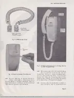
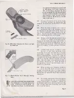
Fig. 1 0-220A Hand Telephone Set Caver and Light
Seal Removed
-........._H5AO HANDSET CORD
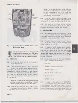
Fig. 1 1 -HSAD Handset Card (Message Waiting
Lamp)
ft
DO NOT USE2012B T RANSFORMER.
The illumination of the
dial
diminishes
w ith increased cord lengths. In
installations where the illumination
ISS 3, SECTION 502-303-101
is considered inadequate, replace 51B
or 53B lamps with their respective
51A or 53A lamps provided the lamp
power
is
supplied by a 2012A transformer
and the combined length of mounting
and handset cords exceed 15 feet.
Refer to Part 5 Maintenance, for
dial
lamp replacement.
3.12
For proper illumination of the dial the length
of the wire between the transformer and
telephone set should not exceed 250 feet of inside
wire.
3.1 3
When the hand telephone set is used in
conjunction with a key telephone system,
the dial lamp can be powered from the 10-volt tap
of a 101G or equivalent power supply of the key
system. If a 10-volt power supply is used, replace
51B or 53B lamps with 51A or 53A lamps.
3.14
Ringing and/ or identification ground, where
required, is common to the lamp circuit.
Damage to the transformer may result if there is
sufficient ground potential difference between
power and telephone grounds. Refer
to
appropriate
section on bonding to power grounds in Division
460.
3.1 5
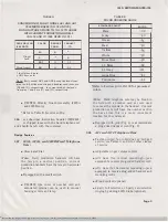
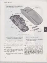
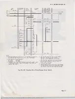
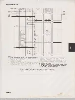
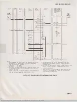
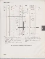
A 426N diode must be installed in either
the AC1 or A D1 base assembly when
connecting for 4-party full selective or 8-party
semiselective ringing. The two leads from the
diode are designated No. 1 and No. 2. Lead No.
1 extends from the flanged (gold) base of the diode;
lead No. 2 extends from the housing tip of the
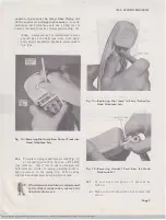
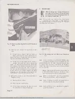
diode. Place the diode in the opening provided in
the terminal board (Fig. 12). Dress the leads to
the appropriate terminal board terminals, refer to
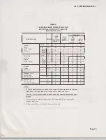
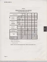
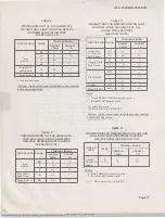
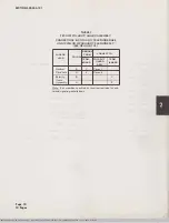
Table D for connections.
3.16
Where extreme noise induction conditions
exist, the 426N diode will not be used.
Instead, a cold-cathode tube or a ringer isolator
installed on a 74A connecting block may be used.
See section on inductive noise for connection
information.
3.17
For portable installations of the AD1 telephone
base, terminate the line and transformer
wiring to 550A jacks or equivalent. Connect the
spade-tipped leads of the mounting cord to a 505A
plug. Connect other end of mounting cord to AD1
base in normal manner.
Page 7
SSP 502·303-101-i03_1972-09-07.jpg Scanned by Frank Harrell, (Cowboy
Frank) Castle Rock, Colorado Jan 31, 2012


