BELINEA 101830 Скачать руководство пользователя страница 6

Settings using the OSD menu

6

With the buttons on the control panel, call up and use the

integrated OSD (On-Screen Display) menu.

The OSD menu is available in different languages. The English

menu names are used in the following description (default setting).

With the OSD function

you can select another

language.

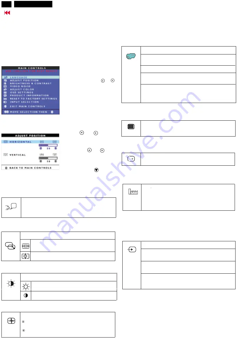
The main menu appears on the screen with icons for the setting

functions.

LANGUAGE

The first symbol (

) is

highlighted.

If necessary, press the

or

button to mark another icon (e.g.

).

Press the MENU button to select

the highlighted icon.

LANGUAGE

ADJUST POSITION

Press the

or

button to

adjust the selected function

(here: HORIZONTAL).

Press the key

or

to

mark another function or press

the MENU key to return to the

main menu.

Select the symbol

(EXIT

MAIN CONTROLS) in the

main menu and press the MENU

key to exit the OSD menu.

The corresponding setting window (here:

)

is displayed.

ADJUST POSITION

Setting language for the OSD menu

Adjusting picture position

?

Calling the ADJUST POSITION setting window

Horizontal picture position ( HORIZONTAL

the picture to the left or to the right

Vertical picture position ( VERTICAL ): Shifting

the picture down or up

): Shifting

Adjusting the brightness and contrast

Calling the BRIGHTNESS & CONTRAST setting window

Setting the brightness of the display

(BRIGHTNESS)

Setting the contrast of the display (

CONTRAST

)

Setting the colour temperature

The "warmth" of the screen colours is set using the colour

temperature. The colour temperature is measured in K (= Kelvin).

Setting the picture quality

Eliminating picture interference (

VIDEO NOISE

)

Eliminating picture noise and horizontal interference

(PHASE)

Eliminate vertical interference with local fuzziness

(CLOCK)

Calling the

ADJUST COLOR

setting window

ORIGINAL PANEL COLOR

= Setting for general

applications (default setting)

9300K FOR CAD/CAM

= Setting for CAD/CAM programmes

6500K FOR IMAGE MANAGEMENT

= Setting, for example,

for image processing

or playing DVDs

USER PRESET

= User - defined setting

In the user

-

defined setting you can change the colour

ratios of the basic colours (red, green, blue) as required.

Setting position for the OSD menu

Calling the

OSD SETTINGS

setting window

You can shift the OSD menu up, down, to the left or to the

right.

Displaying monitor data

You will find the serial number and the current resolution

of this screen in

PRODUCT INFORMATION

.

i

Activating the factory settings

Activating the factory settings

(RESET TO FACTORY

NO

= retain own settings

YES

= Activating the factory settings

With

YES

all monitor settings are reset to the factory settings.

SETTINGS)

Selecting input signal

The monitor can be operated with analog or digital signals. Withthis

function you can (depending on the graphics card you use) switch over

between the analog and the digital mode.

Calling the

INPUT SELECTION

setting window

Switch on the analog mode (

ANALOG DSUB

).The monitor

processes the signals of the analog port (VGA/D

-

SUB).

Switch on the digital mode (

DIGITAL DVI

). The monitor

processes the signals of the digital port (DVI-I).

Switch on analog mode via digital port (

ANALOG DVI

).

The monitor processes the analog signals of the digital

port (DVI -I).

Locking the OSD menu (OSD Lock)

The OSD menu can be locked to prevent accidental or

unauthorised changes to the monitor settings.

Press the MENU button and hold it for approx. 10 seconds.

Please proceed in the same manner to release the locked OSD

menu again.

Setting language for the OSD menu (

)

You can choose from English (default setting), German,

French, Spanish, Italian, and Japanese.

LANGUAGE

Go to cover page

Max 101830

Содержание 101830

Страница 1: ...0 Power Panel C B A 31 Description Page Video Input Diagram Video SW_DDC Diagram 33 Scaler Diagram 34 Frame_Beffer Diagram 35 LVDS Diagram 36 MCU Diagram 37 Scaler Panel C B A 38 39 Inverter Diagram A...

Страница 2: ...ool which is not recommended by Maxdata must first satisfy himself thoroughly that neither his safety nor the safe operation of the equipment will be jeopardized by the service method selected Hereaft...

Страница 3: ...r 256 gray levels 8 bits Backlight CCFL edge light system Active area WxH 359x287 2mm 18 diagonal View angle Horizontal Vertical 160 degree CR 10 Contrast ratio 350 1 White luminance 250 nits Typ 1 2...

Страница 4: ...37 5K 75HZ 31 501 4 640X480 35 0K 67HZ 30 24 5 640X480 31 5K 60HZ 25 175 6 800X600 35 2K 56HZ 36 7 800X600 46 9K 75HZ 49 498 8 800X600 37 9K 60HZ 40 9 832X624 49 7K 75HZ 57 28 MAC 10 1024X768 60 0K 7...

Страница 5: ...wer indicator glows orange when the monitor does not receive a video signal or is in the energy saving mode The power indicator goes off when the monitor is switched off 3 8 Buttons for the OSD menu O...

Страница 6: ...uzziness CLOCK Calling the ADJUST COLOR setting window ORIGINAL PANEL COLOR Setting for general applications default setting 9300K FOR CAD CAM Setting for CAD CAM programmes 6500K FOR IMAGE MANAGEMENT...

Страница 7: ...e description Phenomenon Vertical dim lines Vertical block defect Vertical lines defect Always bright or dark Horizontal block defect Horizontal dim lines Horizontal lines defect Always bright or dark...

Страница 8: ...mputer Having this problem Check the following points Picture disturbances vertical lines Press the AUTO button to conduct the auto adjustment of the screen Set the picture quality in VIDEO NOISE CLOC...

Страница 9: ...ility of display still poor or flicker you may also improve it by manual adjust CLOCK and PHASE functions to eliminate the flicker Step 4 Press the MENU button to bring up MAIN CONTROLS OSD menu Step...

Страница 10: ...connect signal cable on PC side because CPU will detect pin 9 of D SUB 15 pin connector Monitor PC are still ON Bring up CHECK CABLE CONNECTION screen Step 2 Press MENU button for more than 15 seconds...

Страница 11: ...r buttun only untill picture comes on the screen Bring up AGING 1 Buttons for the OSD menu On Screen Display 2 Power indicator 3 Power button 2 3 1 AUTO MENU INPUT ATTENTION CHECK CABLE CONNECTION ATT...

Страница 12: ...G B function can be used on reduce or eliminate snowy noise on the background when the resolution of video signal is 1280 X 1024 vertical 60Hz Slightly increase or decrease the value until snowy nois...

Страница 13: ...e picture tube panel 6 It is recommended that saferty goggles be worn when replacing the picture tube 7 When making adjustments use plastic rather than metal tools This will prevent any short circuit...

Страница 14: ...on 1 2 For Digital inferface Standard Version 3 0 Structure Version 1 3 System and equipment requirements 1 An i486 or above personal computer or compatible 2 Microsoft operation system Windows 95 98...

Страница 15: ...gnized the following error message will appear on the screen as below Please confirm following steps to avoid this message 1 The data structure of EDID was incorrect 2 DDC IC that you are trying to lo...

Страница 16: ...select fill out from Step 1 to Step 9 Step 4 Modify DDC data Monitor Serial No 1 Click Next bring up Fig 15 2 Click Next bring up Fig 16 3 Click OK button to confirm your selection 4 Click icon Read E...

Страница 17: ...Fig 19 3 Click Next bring up Fig 17 6 Click Next bring up Fig 20 7 Click Next bring up Fig 21 Serial number can be filled up or be changed at this moment 4 Click Next bring up Fig 18 5 Click Next bri...

Страница 18: ...ogram Pull down the File menu and select Exit as shown in Fig 27 Step 5 Access Factory Mode for DDC data writing Factory Mode How to Get into Factory Mode Menu Turn off LCD monitor Push AUTO buttons s...

Страница 19: ...n Fig 30 2 Select the DDC2B as the communication channel Disable Factory memory data write for Digital DDC application as shown in Fig 31 3 Click OK button to confirm your selection 4 Click icon Read...

Страница 20: ...e menu and select Exit as shown in Fig 27 Step 7 Save DDC data Sometimes you may need to save DDC data as a text file for using in other IC chip To save DDC data follow the steps below 1 Click Save ic...

Страница 21: ...4 Horizontal active pixels 1024 Aspect Ratio 4 3 Refresh Rate 70 Standard Timing Identification 5 Horizontal active pixels 1280 Aspect Ratio 5 4 Refresh Rate 60 Detailed Timing 1 Pixel Clock MHz 135 H...

Страница 22: ...Rate 70 Standard Timing Identification 5 Horizontal active pixels 1280 Aspect Ratio 5 4 Refresh Rate 60 Detailed Timing 1 Pixel Clock MHz 108 H Active pixels 1280 H Blanking pixels 408 V Active lines...

Страница 23: ...ram Go to cover page Model DJ9B3L 00Z LCD PANEL LCD PANEL MAIN PCB MAIN PCB CONTROL PCB CONTROL PCB SOCKET PCB SOCKET PCB INVERTER PCB INVERTER PCB CN4 CN4 POWER PCB POWER PCB CN1 CN1 1712 1712 CN5 CN...

Страница 24: ...or negative polarity Signal source pattern generator format as attachment table 1 to 32 Reference generator QuantumData 801GD 2 2 Input signal mode Pre set 32 modes P PRESET VIDEO RESOLUTION Resolutio...

Страница 25: ...Sync width 0 080 ms Sync polarity Sync polarity Sync on green 4 3 Check of WHITE D B Apply a 1024 768 60Hz signal with white pattern set brightness control at 100 and contrast control at 70 Adjust th...

Страница 26: ...r Board Check video signals input interface Check inverter panel No Video source Yes Check Inverter panel 700VAC with load No OK Check fluorescent lamp Check main panel No Front control key does not w...

Страница 27: ...rd Main panel 700Vrms Inverter panel Fluorescent Lamp LCD panel 3 3V 5V DC 12V DC 12V DC No power power indicator off Check 12V 3 3V 5V DC Check control panel No No Yes Yes Bad AC adapter Power supply...

Страница 28: ...put 700VAC No Yes Bad Inverter panel Check fluorescent lamp Bad image Check Video fh fv signals Yes Yes Check LCD panel No No Check LCD panel Check all connectors LVDS cable No Check main panel Check...

Страница 29: ...X 0 47 LVDS EO RGB 0 7 3 3V 12V 5V PANEL_PWR_CTL LVDS_SW DSUB_CABLE PWR_BOARD PWR_WIRE DVI_CABLE 04 MEM reserved MEM_DATA 0 47 MEM_ADD 0 11 RAS DQM0 MEM_CLK WE DQM1 CAS CKE 3 3V MEM_SW PANEL 03 GM IR...

Страница 30: ...9 Go to cover page 30 Max 101830 Schematic diagram Power...

Страница 31: ...2115 B3 9019 A3 2107 B2 3192 B2 2116 A3 9021 A3 2108 B2 6081 A3 2117 A3 9022 A2 2109 B2 6107 A3 2118 A3 9023 A1 2110 B2 6108 A2 2121 A3 9024 A2 2114 B2 6112 B1 2123 B1 9025 A2 2119 B3 6113 B3 2124 B2...

Страница 32: ...Power Board C B A 31 Max 101830 Go to cover page...

Страница 33: ...9 Go to cover page 32 Max 101830 Schematic diagram Video Input Schematic diagram DC_Powers...

Страница 34: ...24 2 V div AC 5 mS div 1 V div AC 10 uS div 2 V div AC 5 mS div 2 V div AC 5 uS div 1 V div AC 5 mS div 1 V div AC 10 uS div 2 V div AC 5 uS div 1 V div AC 10 uS div 1 V div AC 5 mS div 1 V div AC 10...

Страница 35: ...9 Go to cover page 34 Max 101830 Schematic diagram Scaler...

Страница 36: ...9 Go to cover page 35 Max 101830 Schematic diagram Frame_Beffer...

Страница 37: ...527 2 12 3523 1 19 3526 2 1 V div AC 5 mS div 1 V div AC 5 uS div 1 V div AC 5 uS div 1 V div AC 0 5 uS div 1 V div AC 5 uS div 1 V div AC 5 uS div 1 V div AC 1 uS div 1 V div AC 5 uS div 1 V div AC 1...

Страница 38: ...38 7401 31 33 7401 9 35 7401 19 34 7401 13 32 7401 8 1 V div AC 10 uS div 1 V div AC 5 mS div 1 V div AC 10 uS div 1 V div AC 5 uS div 1 V div AC 5 mS div 1 V div AC 0 5 mS div 1 V div AC 20 uS div 1...

Страница 39: ...A 2350 A2 A 2351 A2 A 2352 A2 A 2369 A1 A 2370 A2 A 2371 A2 A 2372 A2 A 2373 A2 A 2374 A2 A 2375 A2 A 2376 A2 A 2377 A2 A 2380 A1 A 2381 A1 A 2384 A1 A 2385 A1 A 2386 A1 A 2392 A1 A 2393 A1 A 2398 A1...

Страница 40: ...B 3280 A1 B 3281 A1 B 3282 A1 B 3283 A1 B 3286 A1 B 3291 A1 B 3304 A2 B 3305 A2 B 3306 A1 B 3307 A1 B 3308 A1 B 3309 B2 B 3310 B2 B 3312 B2 B 3313 B2 B 3316 B2 B 3317 B2 B 3318 A2 B 3319 A1 B 3321 A3...

Страница 41: ...1 2 R64 R 294K 1 2 R76 R 511K 1 2 C31 C 104Z 1 2 R81 R NC VIN 1 1 2 R82 R NC 1 2 CP2 CP 1 2 R83 R NC 1 2 CP9 CP 1 2 C37 C NC 1 2 CP10 CP 1 2 R84 R 200K 1 2 R85 R 100K 1 2 C38 C 103J N61 N62 N63 N69 3...

Страница 42: ...470pF 0805 N115 N116 N117 2 10 6 7 3 5 T2 T 20 1400 1 2 3 Q7 Q 3904 1 2 R18 R 1K 0805 1 2 C36 C 105Z 1 2 R36 R 2 2M 5V 1 2 D5 D 4148 SD 1 2 3 Q20 Q 3904 1 2 R21 R 1K 0805 1 2 C39 C 105Z 1 2 R38 R 2 2M...

Страница 43: ...Inverter Diagram PWB AMBIT 9 Go to cover page 42 Max 101830...

Страница 44: ...43 Max 101830 Go to cover page Inverter Diagram PWB AMBIT...

Страница 45: ...44 Max 101830 Go to cover page Schematic diagram Control...

Страница 46: ...ARD REF LABEL SIDE ____ _____ _________ 1712 A4 B GRID BOARD REF LABEL SIDE ____ _____ _________ 1701 A3 B 1702 A3 B 1703 A2 B 1704 A2 B 1705 A1 B 1706 A3 B 1711 A5 B 2701 A5 B 2702 A4 B 3701 A3 B 370...

Страница 47: ...RONT BEZEL ASSY 9322 183 25682 LM181E05 C4M2 LG 3138 157 52151 METAL SHIELDING ASSY 3138 158 55351 SCALER ASSY 3138 158 53481 POWER ASSY 3138 158 54391 METAL FRAM 7P WIRE ASSY 3138 188 73801 DC AC INV...

Страница 48: ...ST R 7205 932217546668 IC M61323FP MITJ R 7206 932202899668 FET POW SM SI4835DY VISH R 7208 935241100118 IC SM 74LVC126AD PHSE R 7212 935245720115 IC SM 74HCT1G14GW PHSE R 7301 932216881671 IC SM GM5...

Страница 49: ...603 X7R 16V 1 N PM10 R 2332 223878615649 CER2 0603 X7R 16V 1 N PM10 R 2333 223878615649 CER2 0603 X7R 16V 1 N PM10 R 2334 223878615649 CER2 0603 X7R 16V 1 N PM10 R 2335 223878615649 CER2 0603 X7R 16V...

Страница 50: ...10K PM5 COL 3457 319802131030 RST SM 0603 10K PM5 COL 3458 319802131030 RST SM 0603 10K PM5 COL 3459 319802131030 RST SM 0603 10K PM5 COL 3461 319802131030 RST SM 0603 10K PM5 COL 3463 319802190030 RS...

Страница 51: ...5 COL R 3110 232271161274 RST SM 1206 RC01 270K PM5 R 3111 319802152240 RST SM 0805 220 K PM5 COL R 3112 213811612209 RST MFLM MFR 5S A22R PM1 A 3113 213811611002 RST MFLM MFR 5S A1K PM1 A 3114 213811...

Страница 52: ...CD industry The CA 110 consists of a main unit and a measuring probe The measuring probe utilizes an optical system suitable for measurement of colour LCDs and is equipped with a viewfinder to verify...

Страница 53: ...52 Max 101830 Go to cover page CA110 Application Continued...

Страница 54: ...sition An image can be seen in the viewfinder but no light will reach the sensor 3 Press 0 CAL If zero calibration is being performed immediately after the POWER switch has been set to ON press 0 CAL...

Страница 55: ...ops Extending the lens barrel fully sets the 25mm measurement area retracting the lens barrel fully sets the 50mm measurement area Use the screwdriver to tighten the lens barrel locking screw and lock...

Страница 56: ...he LCD s display surface move the measuring probe or the LCD until the distance is the correct distance for the measurement area in use o I o I measurement area 25mm 50mm measurement distance 135mm 5m...

Страница 57: ...a MODEL 2250 Measurement viewing selector Measurement viewing selector cover black cover black Fig 8 Fig 9 Fig 10 TURN ON Press 0 CAL Fig 11 Access Factory Mode Factory Mode How to Get into Factory Mo...

Страница 58: ...in Fig 16 example only Probe CA A30 Fig 12 Fig 13 Fig 14 clear image unclear image Fig 15 Fig 16 Measurement viewing selector Measurement viewing selector cover black cover black Step B Brightness Con...

Страница 59: ...value of Y too low increase the value of y firstly experience the value of y too high decrease the value of G the value of x too low decrease the value of R 9300K As shown in Fig 22 23 Value of 9300K...

Страница 60: ...des the full white pattern by Chroma 2250 Check the image of each timing total 14 timings to see if there is any colour s difference on the screen For instance at timing 60K 75Hz 1024x768 as shown in...

Страница 61: ...the soldering iron use suitable pressure and be careful When removing the chip do not use undue force with the pair of tweezers The soldering iron to be used approx 30 W should 1 1 General cautions o...

Страница 62: ...BE RECOVERED TO PRESET MODES USE R FRIENDLY OSD DISPLAY FOR MODE IDENTIFICATION ADJUSTMENT DDC 2B COMMUNICATION CAPABILITY MAX RESOLUTION 1280 1024 NON INTERLACED AT 75 HZ 18 COLOR TFT LCD FLAT PANEL...

Страница 63: ...Video 3 2 Interface 3 2 1 3 3 1 1 1 D sub cable 3 2 2 DVI cable 3 2 3 OSD function control 3 3 Timing requirement 3 3 1 Mode storing capacity 3 3 2 Preset timings 3 3 3 Horizontal scanning 3 3 4 Vert...

Страница 64: ...dimension weight 5 4 2 Block unit palletization 6 0 Environmental characteristics 6 1 Susceptibility of display to external environment 6 2 Transportation tests 6 3 Display disturbances from external...

Страница 65: ...ray levels 8 bits Backlight CCFL edge light system Active area WxH 359x287 2mm 18 diagonal View angle Horizontal Vertical 160 degree CR 10 Contrast ratio 350 1 White luminance 250 nits Typ 2 2 Scannin...

Страница 66: ...sync Positive Negative Ver sync Positive Negative Composite sync TTL level input impedance 2k2 ohm terminate Positive Negative Sync on green video 0 3 Vp p Negative Video 0 7 Vp p Positive 2 Intel DVI...

Страница 67: ...ield 4 NC 5 NC 6 DDC clock 7 DDC data 8 Analog V sync 9 TMDS data1 10 TMDS data1 11 TMDS data1 shield 12 NC 3 2 Interface 3 2 1 D Sub Cable Length 1 8 M 50 mm fixed Connector type D sub male with DDC2...

Страница 68: ...C1 Analog R C2 Analog G C3 Analog B C4 Analog H sync C5 Analog GND Analog R G B return MAIN CONTROLS LANGUAGE ADJUST POSITION BRIGHTNESS CONTRAST VIDEO NOISE ADJUST COLOR OSD SETTINGS PRODUCT INFORMAT...

Страница 69: ...nt VIDEO NOISE Phase adjustment Clock adjustment ADJUST COLOR Original panel color 9300K for CAD CAM 6500K for image management User preset red green blue adjust OSD POSITION OSD H position OSD V posi...

Страница 70: ...SH ESPANOL FRANCAIS DEUTSCH ITALIANO JAPANESE ADJUST POSITION HORIZONTAL VERTICAL BRIGHTNESS CONTRAST brightness and contrast adjustment OSD POSITION OSD H position OSD V position PRODUCT INFORMATION...

Страница 71: ...86 3 line 0 317 10 line 0 029 1 line SYNC H V POLARITY SEP SYNC Y Y Y Y MODE NO 1 2 3 4 RESOLUTION 640 x 350 720 x 400 640 x 480 640x480 Dot clock MHz 25 175 28 321 31 501 36 f h 31 469kHz 31 468kHz 3...

Страница 72: ...600 lines 12 80 768 lines 15 880 768 lines 13 599 768 lines S ms 0 770 37 line 0 017 1 line 0 062 3 lines 0 053 3 lines SYNC H V POLARITY SEP SYNC Y Y Y Y MODE NO 9 10 11 12 RESOLUTION 800 x 600 800...

Страница 73: ...nes 12 533 900 lines S ms 0 074 4 lines 0 043 4 line 0 033 2 line 0 028 2 lines SYNC H V Serr POLARITY SEP SYNC Y Y Y Y MODE NO 17 18 19 20 RESOLUTION 1024 x 768 1024 x 768 1152 x 8 64 1152 x 864 Dot...

Страница 74: ...4 lines 17 972 556 lines S ms 0 012 1 line 0 024 2 lines 0 028 2 lines 0 672 21 lines SYNC H V POLARITY SEP SYNC Y Y Y Y MODE NO 25 26 27 28 RESOLUTION 1280 x 960 1280 x 960 1280 x 1024 1280 x 1024 Do...

Страница 75: ...ote Disconnect DVI signal cable and audio module STATUS Horizontal Vertical Power Spec LED On Pulse Pulse as normal on Green Stand by No Pulse Pulse 2 W Amber Suspend Pulse No Pulse 2 W Amber off No P...

Страница 76: ...80X1024 64 0K 60HZ 108 14 1280X1024 80 0K 75HZ 135 15 1280X1024 81 1K 76HZ 135 008 SUN Mode I 16 688X556 31 25K 50HZ 27 TV PAL 4 0 Visual characteristics 4 1 Test conditions Unless otherwise specified...

Страница 77: ...1 Actual display size 359x287mm 4 5 Brightness uniformity Set contrast at 70 and turn the brightness to get average above 200 nits at center of the screen Apply the Fig 1 it should comply with the fo...

Страница 78: ...nter should be 9300K CIE coordinates X 0 281 0 020 Y 0 311 0 020 6500K CIE coordinates X 0 312 0 020 Y 0 338 0 020 5 0 Mechanical characteristics 5 1 Controls Front side DC power switch OSD function k...

Страница 79: ...iner 20 feet 40 feet 10 21 6 0 Environmental characteristics The following sections define the interference and susceptibility condition limits that might occur between external environment and the di...

Страница 80: ...st Test electrical function ok Result mechanical function ok no serious damage on set appearance For design evaluation only operating 10 G 11 msec 1000 cycles Bump temperature 23 C Test humidity 60 ai...

Страница 81: ...5 major 2 50 minor please also refer to annual quality agreement Customer acceptance criteria UAW0377 00 9 0 Serviceability The serviceability of this monitor should fulfill the requirements which are...

Страница 82: ...level Fig 3 Cross talk Pattern Center at Gray level 0 Black GENERAL PRODUCT SPECIFICATION Continued 01 11 09 01 11 09 590 21 23 EDWARD CHANG 18 TFT SXGA LCD CMTR HP 81 Max 101830 YB 1 2 1 2 1 6 1 3 1...

Страница 83: ...Continued 01 11 09 01 11 09 590 22 23 EDWARD CHANG 18 TFT SXGA LCD CMTR HP D VIDEO C E SEPARATE SYNC HORIZONTAL B A R VIDEO Q S P O D VIDEO C E B A VERTICAL HORIZONTAL COMPOSITE SYNC FIG 4 TIMING CHA...

Страница 84: ...SPECIFICATION Continued 01 11 09 01 11 09 590 23 23 EDWARD CHANG 18 TFT SXGA LCD CMTR HP D VIDEO C E B A VERTICAL COMPOSITE SYNC FIG 5 TIMING CHART 2 O P Q R S VIDEO B S P Q O R SYNC ON GREEN HORIZON...

Страница 85: ...d and thereafter be maintained throughout the test period 2 1 3 The mains switch es must be in the ON position 2 2 Test Requirements All products should be HiPot and Ground Continuity tested as follow...

Отзывы: