800-543-9038
USA
866-805-7089
CANADA
203-791-8396
LATIN AMERICA
27
W278_08
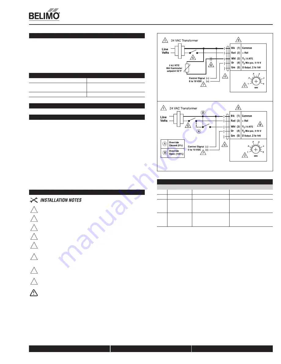
Standard Economizer Mode Wiring AF24-ECON-R03 US
W279_08
Override for AF24-ECON-R03 US
Override control
Wire Input Signal
Position
Application
Y1
24 VAC
Drive closed (0%)
Morning warm-up cycle
Y1
Common
Drive open (100%)
Smoke Purge
Y1
Open wire
Drive to min position
Mechanical cooling in use,
RTU thermostat
calls for heat
Y2
0 VDC to
10 VDC
Min position of
0% to 100%
Override potentiometer via a
remote CO2 sensor/control-
ler or DDC controller
AF24-ECON-R03 US
Proportional Damper Actuator, Spring Return Safety, 24V for Stand-alone Economizer Damper Control using 3 k
7
Mixed Air Sensor, Built-in Minimum Position Adjustment. Output Signal of 2 to 10VDC for Position Indication.
Occupied - Economizer Mode
The AF24-ECON-R03 US enters Economizer Mode when either an external relay
or controller completes the circuit between the actuator wire 3(Y1) and MA
sensor. In this mode, the actuator moves proportionally to maintain a MA set-
point of 55°F (fixed). A proportional band of 6°F modulates the actuator between
53 and 58°F. Also, a +/-1°F dead band eliminates hunting of the actuator, while
maintaining suitable temperatures in the RTU mixed air chamber.
MA Dry Bulb Temperature
AF24-ECON... Position
< 53°F
Min. position
53°F < MAT < 58°F
Modulates between
Min. Position and 100% open
> 58°F
100% open
Accessories, see page 308.
Typical Specification
Spring return control damper actuators shall be direct coupled type which
require no crankarm and linkage and be capable of direct mounting to a shaft up
to a 1.05” diameter. Actuator shall deliver a minimum output torque of 133
in-lbs. The actuator must provide proportional damper control in response to a
3 k
7
NTC thermistor, 55°F setpoint. Actuator must have a built-in minimum
position potentiometer. Actuator must have minimum position override via 0 to
10 VDC on wire 4. Actuators shall use a brushless DC motor controlled by a
microprocessor and be protected from overload at all angles of rotation. Run
time shall be independent of torque load. A 2 to 10 VDC feedback signal shall be
provided for position feedback or master-slave applications. The actuator must
be designed so that they may be used for either clock-wise or counterclockwise
fail safe operation. Actuators shall be cUL Approved, have a 5 year warranty, and
be manufactured under ISO 9001 International Quality Control Standards.
Actuators shall be as manufactured by Belimo.
Wiring Diagrams
1
Provide overload protection and disconnect as required.
2
Min-position is adjustable from 0 to 100% with a
potentiometer on the actuator cover.
3
Actuators with plenum rated cable do not have numbers on wires; use
color codes instead.
4
CW (default) indicates that motor drive starts at zero position.
5
A relay or switch can spring return the actuator when the RTU fan de-
energizes, or if low ambient temperature is sensed.
6
A standard relay can be used to close the sensor circuit to engage
economizer mode, e.g. outside air changeover device like a dry bulb or
enthalpy limit switch.
7
A remote CO2 sensor or DDC controller with a 0 to 10 VDC output can
change the standard relay can be used to open and close the sensor
circuit. This device can be a relay or a dry bulb/enthalpy limit switch.
8
Override control for Y2 only accepts 0 to 10 VDC override control.
WARNING
Live Electrical Components!
During installation, testing, servicing and troubleshooting of this product, it maybe
necessary to work with live electrical components. Have a qualified licensed electrician
or other individual who has been properly trained in handling live electrical components
perform these tasks. Failure to follow all electrical safety precautions when exposed to live
electrical components could result in death or serious injury.
K20901 - 01/09 - Subject to change. © Belimo Air
controls (USA), Inc.


