background image

Installation RS20/22/30/32/40

Release 07 10/2021

39

100 Mbit/s half-duplex mode, 100 Mbit/s full duplex mode

10 Mbit/s half-duplex mode, 10 Mbit/s full duplex mode

Delivery state: Autonegotiation activated
The port casing is electrically connected to the front panel.
The pin assignment corresponds to MDI-X.

1.3.2

10/100 Mbit/s twisted pair port

This port is an RJ45 socket.
The 10/100 Mbit/s twisted pair port allows you to connect network 
components according to the IEEE 802.3 10BASE-T/100BASE-TX standard.
This port supports:

Autonegotiation 

Autopolarity 

Autocrossing (if autonegotiation is activated)

100 Mbit/s half-duplex mode, 100 Mbit/s full duplex mode

10 Mbit/s half-duplex mode, 10 Mbit/s full duplex mode

Delivery state: Autonegotiation activated
The port casing is electrically connected to the front panel.

Pin

Function

1

BI_DB+

2

BI_DB-

3

BI_DA+

4

BI_DD+

5

BI_DD-

6

BI_DA-

7

BI_DC+

8

BI_DC-

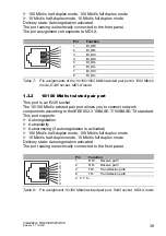
Table 7:

Pin assignments of the 10/100/1000 Mbit/s twisted pair port in 1000 Mbit/s 
mode, RJ45 socket, MDI-X mode

Pin

Function

1

RD+

Receive path

2

RD-

Receive path

3

TD+

Transmission path

6

TD-

Transmission path

4, 5, 7, 8 –

Table 8:

Pin assignment 10/100 Mbit/s twisted pair port, RJ45 socket, MDI-X mode

1
2
3
4
5
6
7
8

1
2
3
4
5
6
7
8

Содержание Hirschmann RS20 Series

Страница 1: ... USB P Stand by FAULT RM ON RS20 LS DA RM 24V P1 0V 0V FAULT 24V P2 Stand by Aufkleber MAC Adresse IP ADDRESS 2 LS DA 1 3 5 7 4 6 8 V 24 USB P Stand by FAULT RM ON RS20 RM Stand by Aufkleber MAC Adresse IP ADDRESS V 24 USB P Stand by FAULT RM ON LS 1 DA LS 2 DA LS 3 DA LS 4 DA RS20 0800 RS20 2400 RS20 0400 RM Stand by Aufkleber MAC Adresse IP ADDRESS V 24 USB P Stand by FAULT RM ON RM Stand by Auf...

Страница 2: ...se The performance features described here are binding only if they have been expressly agreed when the contract was made This document was produced by Hirschmann Automation and Control GmbH according to the best of the company s knowledge Hirschmann reserves the right to change the contents of this document without prior notice Hirschmann can give no guarantee in respect of the correctness or acc...

Страница 3: ...40 35 1 2 Device variants with PoE optional 36 1 2 1 Number of ports and media for devices with PoE 36 1 2 2 PoE power units 38 1 3 Ethernet ports 38 1 3 1 10 100 1000 Mbit s twisted pair port 38 1 3 2 10 100 Mbit s twisted pair port 39 1 3 3 10 100 Mbit s twisted pair connection PoE RS22 RS32 40 1 3 4 1000 Mbit s F O port 40 1 3 5 100 Mbit s F O port 41 1 3 6 Gigabit combo port 41 1 4 Display ele...

Страница 4: ...53 2 5 2 RS22 RS32 supply voltage and signal contact 54 2 6 Mounting the terminal block 57 2 7 Connecting the ferrite 57 2 8 Operating the device 58 2 9 Connecting data cables 58 2 10 Filling out the inscription label 58 3 Making basic settings 59 3 1 Applies to devices with a software version before HiOS 7 1 8 1 59 3 1 1 Default settings 59 4 Monitoring the ambient air temperature 60 5 Maintenanc...

Страница 5: ...ble injury or death If this symbol is displayed in addition to a safety instruction of the type Danger or Warning it means that there is a danger of electric shock and failure to observe the instructions will inevitably result in injury This symbol indicates the danger of hot surfaces on the device In connection with safety instructions non observance of the instructions will inevitably result in ...

Страница 6: ...6 Installation RS20 22 30 32 40 Release 07 10 2021 NOTICE NOTE provides information about procedures that do not involve the risk of injury ...

Страница 7: ...d in the Hirschmann product information including this manual Operate the device solely according to the technical specifications See Technical data on page 64 Installation site requirements Install the device in a fire enclosure according to IEC 60950 1 If installed in a living area or office environment the device must be operated only in switch cabinets with fire protection characteristics acco...

Страница 8: ...ventilation slits free to ensure good air circulation See General technical data on page 64 Mount the device in the vertical position At ambient air temperatures 60 C 140 F The surfaces of the device housing may become hot Avoid touching the device while it is operating Qualification requirements for personnel Only allow qualified personnel to work on the device Qualified personnel have the follow...

Страница 9: ...afety Extra low Voltage SELV Connect only SELV circuits with voltage restrictions according to IEC 60950 1 or ES1 according to IEC EN 62368 1 to the supply voltage connections and to the signal contacts Exclusively connect a supply voltage that corresponds to the type plate of your device Applies exclusively to RS20 RS30 RS40 device variants For power supply via DC voltage All following prerequisi...

Страница 10: ... voltage sources the combined supply voltages must fulfill the requirements of the National Electrical Code Table 11 b Relevant for North America For use in class 2 circuits Use 60 75 C 140 167 F or 75 C 167 F copper Cu wire only Relevant for North America for devices certified for hazardous locations Power input and output I O wiring must be in accordance with Class I Division 2 wiring methods Ar...

Страница 11: ...stall a suitable input fuse in the following cases The neutral conductor or the negative terminal of the supply voltage is ungrounded For the supply voltage you provide a DC voltage greater than 125 V DC See General technical data on page 64 With AC power supply use a cable cross section of at least 0 75 mm for North America AWG 18 for the current conductor at the voltage input With DC power suppl...

Страница 12: ...C Ta 60 C for T or E types position 14 of nomenclature breakdown T4 0 C Ta 60 C for S types position 14 of nomenclature breakdown The device shall be installed in a suitable enclosure in accordance with EN 60079 0 providing a degree of protection of at least IP54 taking into account the environmental conditions under which the equipment will be used When the temperature under rated conditions exce...

Страница 13: ...0 and RS30 types T4 0 C Ta 60 C for S types position 14 of nomenclature breakdown or T4 40 C Ta 70 C for T or E types position 14 of nomenclature breakdown Temperature class and code for RS22 and RS32 types T4 40 C Ta 50 C for T or E types position 14 of nomenclature breakdown or T4 0 C Ta 50 C for S types position 14 of nomenclature breakdown Temperature class and code for RS40 types T3 40 C Ta 7...

Страница 14: ...ational Electrical Code NFPA 70 and in accordance with the authority having jurisdiction SUITABLE FOR USE IN CLASS I DIVISION 2 GROUPS A B C AND D HAZARDOUS LOCATIONS OR NON HAZARDOUS LOCATIONS ONLY WARNING EXPLOSION HAZARD SUBSTITUTION OF ANY COMPONENTS MAY IMPAIR SUITABLE FOR CLASS I DIVISION 2 WARNING EXPLOSION HAZARD DO NOT DISCONNECT EQUIPMENT WHILE THE CIRCUIT IS LIVE OR UNLESS THE AREA IS K...

Страница 15: ...PAIR SUITABILITY FOR HAZARDOUS LOCATIONS OR EXPLOSIVE ATMOSPHERES WARNING EXPLOSION HAZARD DO NOT DISCONNECT EQUIPMENT UNLESS POWER HAS BEEN SWITCHED OFF OR THE AREA IS KNOWN TO BE NON HAZARDOUS DO NOT OPEN WHEN ENERGIZED CONTROL DRAWING for RS20 RS22 RS30 RS32 and RS40 Family Size A4 Document No 000157671DNR Rev 0 Date 2011 09 21 Sheet 1 of 1 NON HAZARDOUS LOCATION USB Port for Auto Configuration...

Страница 16: ... 60 C for S types position 14 of nomenclature breakdown or T4 40 C Ta 70 C for T or E types position 14 of nomenclature breakdown Temperature class and code for RS22 and RS32 types T4 40 C Ta 50 C for T or E types position 14 of nomenclature breakdown or T4 0 C Ta 50 C for S types position 14 of nomenclature breakdown Temperature class and code for RS40 types T3 40 C Ta 70 C for T or E types posit...

Страница 17: ...ing to radio interference from motor vehicles Certified devices are marked with an e1 type approval indicator For use in connection with a suitable type approved power supply only CE marking The labeled devices comply with the regulations contained in the following European directive s 2011 65 EU and 2015 863 EU RoHS Directive of the European Parliament and of the Council on the restriction of the...

Страница 18: ...ontrol GmbH Stuttgarter Str 45 51 72654 Neckartenzlingen Germany You find the EU conformity declaration as PDF file for downloading on the Internet at https www doc hirschmann com certificates html The device can be used in industrial environments Interference immunity EN 61000 6 2 Emitted interference EN 55032 Warning This is a class A device This device can cause interference in living areas and...

Страница 19: ...ound to comply with the limits for a Class A digital device pursuant to part 15 of the FCC Rules These limits are designed to provide reasonable protection against harmful interference when the equipment is operated in a commercial environment This equipment generates uses and can radiate radio frequency energy and if not installed and used in accordance with the instruction manual may cause harmf...

Страница 20: ...0 22 30 32 40 Release 07 10 2021 About this Manual The Installation user manual contains a device description safety instructions a description of the display and the other information that you need to install the device ...

Страница 21: ...Installation RS20 22 30 32 40 Release 07 10 2021 21 Key The symbols used in this manual have the following meanings Listing Work step Subheading ...

Страница 22: ...voltage is supplied redundantly The following installation options are available Mounting on the DIN rail mounting them on a wall only RS22 RS32 Depending on the device variant you can choose various media to connect terminal devices and other infrastructure components Twisted pair cable Multimode F O Singlemode F O The twisted pair ports support Autocrossing Autonegotiation Autopolarity There are...

Страница 23: ...necting segments The table below shows three port categories for each product variant uplink ports PoE ports and other ports The table also shows for each product category the number of ports you can select and the type of ports In the column for the port type the abbreviations F O optical fiber and TP twisted pair indicate the media type while the abbreviations DSC ST SFP and RJ45 indicate the so...

Страница 24: ...bit s F O SFP 6 14 22 10 100 Mbit s TP RJ45 4 10 100 Mbit s TP RJ45 RS40 4 Ports 1 to 4 4 combo ports 100 1000 Mbit s F O SFP 10 100 1000 Mbit s TP RJ45 5 10 100 1000 Mbit s TP RJ45 Position Characteristic Ident Ident 2 a Property 1 to 4 Product RS20 Rail Switch without gigabit ports RS30 Rail Switch with gigabit ports RS22 Rail Switch without gigabit ports with PoEb c RS32 Rail Switch with gigabi...

Страница 25: ...SA 12 12 01 UL 1604 GL Railway along track Substation Bab CE UL 508 ISA 12 12 01 UL 1604 GL Railway along track Substation Hazardous Location ATEX IECEx 17 Software variant E Enhanced P Professional a For device variants with 2 uplink ports you use the Ident column for items 10 11 and for items 12 13 For device variants with 3 uplink ports you use the Ident 2 column for items 10 11 and the Ident c...

Страница 26: ...RS32 is 50 C 122 F v Not when using GG or G2 transceivers w The extended T temperature range for the PoE capable devices is 40 C to 60 C 40 F to 140 F With a UL 508 ATEX IECEx or ISA 12 12 01 approval the maximum operating temperature for the extended T temperature range for PoE capable devices RS22 RS32 is 50 C 122 F x Not when using GG or G2 transceivers y In combination with 2nd uplink port ZZ ...

Страница 27: ...olumn 3 T T Temperature range Extended 40 C to 70 C 40 F 158 F D D Voltage range 9 6 V DC to 60 V DC or 18 V AC to 30 V AC A A Approvals CE UL 508 ISA 12 12 01 UL 1604 E E Software variant Enhanced Position Characteristic Ident Property 1 to 4 Product RS40 Rail Switch with gigabit ports 5 hyphen 6 to 7 Number of 10 100 Mbit s Ports 00 0 10 100 Mbit s Ethernet 8 and 9 Number of 1000 Mbit s Ports 09...

Страница 28: ... 09 09 9 1000 Mbit s Ethernet ports CC CC Port 1 2 Combo port SFP slot 100 1000 Mbit s alternatively RJ45 connector 10 100 1000 Mbit s CC CC Port 3 4 Combo port SFP slot 100 1000 Mbit s alternatively RJ45 connector 10 100 1000 Mbit s E E Temperature range Extended 40 C to 70 C 40 F to 158 F with Conformal Coating D D Voltage range 9 6 V DC to 60 V DC or 18 V AC to 30 V AC A A Approvals CE UL 508 I...

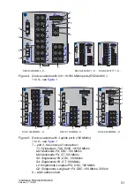
Страница 29: ... s S2 Singlemode FX DSC 100 Mbit s S4 Singlemode FX ST 100 Mbit s L2 Singlemode Longhaul FX DSC 100 Mbit s G2 Singlemode Longhaul FX DSC 100 Mbit s 200 km 8 MAC address field 9 IP address field RS20 RM Stand by Aufkleber MAC Adresse IP ADDRESS V 24 USB P Stand by FAULT RM ON LS 1 DA LS 2 DA LS 3 DA LS 4 DA 1 2 3 4 5 6 7 7 8 9 RS20 0400T1T1 D RS20 0400M2T1 D RS20 RM Stand by Aufkleber MAC Adresse I...

Страница 30: ...M ON RS20 0800T1T1 D RS20 RM 24V P1 0V 0V FAULT 24V P2 Stand by Aufkleber MAC Adresse IP ADDRESS LS DA 1 3 5 7 4 6 8 V 24 USB P Stand by FAULT RM ON DA 2 LS RS20 0800M2T1 D RS20 LS DA RM 24V P1 0V 0V FAULT 24V P2 Stand by Aufkleber MAC Adresse IP ADDRESS 2 LS DA 1 V 24 USB P Stand by FAULT RM ON 3 5 7 9 4 6 8 10 11 13 15 12 14 16 RS20 RM 24V P1 0V 0V FAULT 24V P2 Stand by Aufkleber MAC Adresse IP ...

Страница 31: ...IP ADDRESS 3 5 7 9 11 13 15 17 4 6 8 10 12 14 16 18 19 21 23 20 22 24 V 24 USB P Stand by FAULT RM ON LS DA 1 2 DA LS RS20 RM 24V P1 0V 0V FAULT 24V P2 Stand by Aufkleber MAC Adresse IP ADDRESS 1 3 5 7 9 11 13 15 2 4 6 8 10 12 14 16 17 19 21 23 18 20 22 24 V 24 USB P Stand by FAULT RM ON 1 2 3 4 5 6 6 6 7 8 9 7 RS20 2400M2M2 D RS20 2400M2T1 D RS20 2400T1T1 D RS20 24V P1 0V 0V FAULT 24V P2 4 6 8 10...

Страница 32: ...V 24 connection for external management 6 ports in compliance with 10 100BASE T X RJ45 connections 7 port 1 port 2 free choice of connections T1 Twisted pair T X RJ45 10 100 1000 Mbit s O6 SX LX SFP slot 1000 Mbit s 8 MAC address field 9 IP address field RS30 RM 24V P1 0V 0V FAULT 24V P2 Stand by Aufkleber MAC Adresse IP ADDRESS 3 5 7 9 4 6 8 10 V 24 USB P Stand by FAULT RM ON DA 2 LS DA 1 LS RS30...

Страница 33: ... by Aufkleber MAC Adresse IP ADDRESS V 24 USB P Stand by FAULT RM ON 3 5 7 9 4 6 8 10 11 13 15 17 12 14 16 18 LS DA 1 LS DA 2 RS30 1602T1T1 D RS30 1602O6O6 D RS30 1602O6T1 D 1 2 3 4 5 6 6 6 7 8 9 7 RS30 RM 24V P1 0V 0V FAULT 24V P2 Stand by Aufkleber MAC Adresse IP ADDRESS 3 5 7 9 11 13 15 17 4 6 8 10 12 14 16 18 19 21 23 25 20 22 24 26 V 24 USB P Stand by FAULT RM ON 2 DA LS 1 DA LS RS30 RM 24V P...

Страница 34: ...S30 24V P1 0V 0V FAULT 24V P2 5 7 9 11 6 8 10 12 13 15 17 14 16 18 RS30 24V P1 0V 0V FAULT 24V P2 5 7 9 6 8 10 LS DA 1 LS DA 2 LS DA 3 LS DA 4 LS DA 1 LS DA 2 LS DA 3 LS DA 4 LS DA 1 LS DA 2 LS DA 3 LS DA 4 RM Stand by Aufkleber MAC Adresse IP ADDRESS V 24 USB P Stand by FAULT RM ON RM Stand by Aufkleber MAC Adresse IP ADDRESS V 24 USB P Stand by FAULT RM ON RM Stand by Aufkleber MAC Adresse IP AD...

Страница 35: ... Alternatively T X RJ45 connections 10 100 1000 Mbit s 7 ports in compliance with 10 100 1000BASE T X RJ45 connections RS40 24V P1 0V 0V FAULT 24V P2 1 3 5 7 2 4 6 8 1 2 3 4 RM Stand by Aufkleber MAC Adresse IP ADDRESS V 24 USB P Stand by FAULT RM ON 9 1 2 3 4 5 6 7 7 6 8 9 RS40 0009CCCCSD RS40 24V P1 0V 0V FAULT 24V P2 1 3 5 7 2 4 6 8 1 2 3 4 RM Stand by Aufkleber MAC Adresse IP ADDRESS V 24 USB ...

Страница 36: ...E example RS22 1700MMM2 P 1 to 5 and 7 to 9 see figure 5 6 ports in compliance with 10 100BASE T X RJ45 connections the PoE capable ports 14 to 17 are indicated accordingly RS22 RM Stand by Aufkleber MAC Adresse IP ADDRESS V 24 USB P Stand by FAULT RM ON 1 2 3 4 5 6 6 6 LS DA 2 LS DA 1 LS DA 3 7 9 8 10 9 4 6 8 10 5 7 9 11 12 14 16 13 15 17 RS22 1700MMM2 P FAULT 48V P1 0V 0V 48V P2 ...

Страница 37: ...r 10BASE T 100BASE TX ports RJ45 sockets for connecting network segments or PoE terminal devices PD Powered Device for all IEEE802 3af classes up to a maximum power output of 15 4 W The four PoE capable ports are the four bottom ports on the right side of the device see figures in section Number of ports and media for devices with PoE on page 36 The PoE ports are indicated in red on the device The...

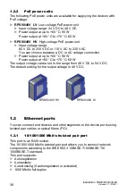
Страница 38: ...put at up to 60 C 90 W Power output at 60 C to 70 C 60 W The output voltage can be set in the range from 48 V DC to 54 V DC The default setting for the output voltage is 48 V DC 1 3 Ethernet ports You can connect end devices and other segments to the device ports using twisted pair cables or optical fibers F O 1 3 1 10 100 1000 Mbit s twisted pair port This port is an RJ45 socket The 10 100 1000 M...

Страница 39: ...This port supports Autonegotiation Autopolarity Autocrossing if autonegotiation is activated 100 Mbit s half duplex mode 100 Mbit s full duplex mode 10 Mbit s half duplex mode 10 Mbit s full duplex mode Delivery state Autonegotiation activated The port casing is electrically connected to the front panel Pin Function 1 BI_DB 2 BI_DB 3 BI_DA 4 BI_DD 5 BI_DD 6 BI_DA 7 BI_DC 8 BI_DC Table 7 Pin assign...

Страница 40: ...plied via the wire pairs transmitting the signal phantom voltage 1 3 4 1000 Mbit s F O port This port is an SFP slot The 1000 Mbit s F O port offers you the ability to connect network components according to the IEEE 802 3 100BASE SX 1000BASE LX standard This port supports This port supports Autonegotiation For device variants with the designation RS30 02OOZZ and RS32 02OOZZ 4 uplink ports with SF...

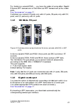
Страница 41: ...o the IEEE 802 3 100BASE FX standard This port supports Full or half duplex mode Default setting Full duplex Note Verify that the LH ports are connected only with LH ports SM ports only with SM ports and MM ports only with MM ports 1 3 6 Gigabit combo port You have the option of alternatively connecting a twisted pair cable via a RJ45 socket or an optical fiber via a SFP transceiver to a combo por...

Страница 42: ...et up the software starts and initializes itself Afterwards the device performs a self test During this process various LEDs light up The process takes around 60 seconds Device state These LEDs provide information about conditions which affect the operation of the whole device Figure 14 Device status LEDs Media type Connection options Twisted pair cable Technical standard IEEE 802 3 10BASE T 100BA...

Страница 43: ...y of the signal contact position Glowing red The signal contact is open i e it is reporting a detected error Not glowing The signal contact is closed i e it is not reporting a detected error RM Redundancy Manager green yellow LED Glowing green RM function active redundant port disabled Glowing yellow RM function active redundant port enabled Not glowing RM function not active Flashing green Incorr...

Страница 44: ...inal emulation or an AutoConfiguration Adapter ACA 11 This enables you to set up a connection to the Command Line Interface CLI and to the system monitor The interface casing is electrically connected to the front panel LS link status green LED Not glowing No valid connection Glowing green Valid connection Flashing green 1 time a period Port is switched to stand by Flashing green 3 times a period ...

Страница 45: ...e V 24 interface is not electrically insulated from the supply voltage Figure 16 Pin assignment of the V 24 interface and the DB9 plug Note The Terminal cable is available as an accessory 1 1 8 5 6 2 3 5 1 2 3 4 5 6 CTS n c TX GND RX RTS RJ11 DB9 RJ11 DB9 ...

Страница 46: ...ce is ready for operation Perform the following steps to install and configure the device Checking the package contents Installing and grounding the device Installing an SFP transceiver optional Adjust DIP switch settings Connecting the terminal block Connecting the ferrite Mounting the terminal block Operating the device Connecting data cables Filling out the inscription label ...

Страница 47: ...fy that the device maintains the minimum clearance to meet the climatic conditions during operation Top and bottom device side 10 cm 3 94 in Left and right device side 2 cm 0 79 in WARNING FIRE HAZARD Install the device in a fire enclosure according to IEC 60950 1 Failure to follow this instruction can result in death serious injury or equipment damage WARNING ELECTRIC SHOCK Install this device on...

Страница 48: ...n accessory can be used to avoid excessive resonance You must use the Open Rail Mounting Kit with the order number 942 007 001 when mounting your RS30 0802 device on ships If you have very little space on your DIN rail you can alternatively use Open Rail Mounting Kit 942 007 101 for mounting DIN rail on DIN rail Mount one mounting kit on each side of your RS30 0802 device but at least one mounting...

Страница 49: ...cal flat surface Applies to the device variants RS22 and RS32 You have the option of attaching the device to a vertical flat surface This requires a wall mounting plate which you purchase as a separate accessory See Accessories on page 77 Verify that the device maintains the minimum clearance to meet the climatic conditions during operation Top and bottom device side 10 cm 3 94 in Left and right d...

Страница 50: ...late see on page 77 Accessories on a level wall surface using 4 screws 2 2 4 Grounding the device Use a wire diameter for the ground conductor that is no smaller than the diameter of the supply voltage connection however of at least 1 0 mm AWG16 With the RS20 RS30 RS40 the front panel of the device is grounded via the separate ground screw With the RS22 RS32 the front panel and the metal housing o...

Страница 51: ... protection cap from the SFP transceiver 2 Push the SFP transceiver with the lock closed into the slot until it latches in 3 2 4 Adjust DIP switch settings The 2 pin DIP switch on the front panel of the device gives you the following options Figure 19 2 pin DIP switch Switch RM Position Switch Stand by Position Ring redun dancy Coupli ng switch Redund ancy manager Coupli ng manag er Ring port Cont...

Страница 52: ...of your device Never insert sharp objects small screwdrivers wires etc into the connection terminals for electric conductors and do not touch the terminals Observe the maximum values for the contact load of the signal contact Failure to follow this instruction can result in death serious injury or equipment damage WARNING FIRE HAZARD When supplying with direct current DC exclusively ground the neg...

Страница 53: ... 6 pin terminal block 1 DC voltage voltage range 9 6 V DC to 60 V DC 2 AC voltage voltage range 18 V AC to 30 V AC With a non redundant supply of the supply voltage the device reports the loss of a supply voltage You can prevent this message by changing the configuration in the Management Signal contact for RS20 RS30 RS40 The signal contact FAULT pin assignment of terminal block see figure 20 is u...

Страница 54: ...90 48V LV and RPS90 48V HV power units from Hirschmann Only use these power units to ensure that the specifications are fulfilled Make sure that the external power supply unit you use to provide the PoE voltage fulfills the following basic prerequisites Insulation requirements according to IEEE 802 3af insulation resistance 48 V output to rest of the world 2 250 V DC for 1 min Output power 100 W C...

Страница 55: ...he neutral conductor or the minus terminal of the supply voltage is not grounded install a suitable fuse in the input line For supply voltages 125 V DC Install a suitable external fuse in the supply voltage input line of the plus terminal Use a supply cable with a maximum length of 2 m 6 56 ft to the power unit Figure Pin Assignment Supply voltage range 1 Protective conductor High voltage input vo...

Страница 56: ...ction monitoring in the management You can also use the switch Web page to switch the signal contact manually and thus control external devices The potential free signal contact relay contact closed circuit reports through a break in contact The detected inoperability of at least one of the two voltage supplies voltage supply 1 or 2 is below the threshold value The device is not operational The fa...

Страница 57: ...minal block Mount the terminal block for the voltage supply and signal contact on the front of the device using the snap lock Verify that the snap lock latches in place 2 7 Connecting the ferrite Note For PoE devices with 16 or more ports RS22 16 RS22 17 RS22 24 and RS22 25 To adhere to EMC conformity you connect the ferrite supplied to the voltage input via the power supply cable Insert both cabl...

Страница 58: ...cables and data cables do not run parallel over longer distances To reduce inductive coupling verify that the power supply cables and data cables cross at a 90 angle Use shielded data cables for gigabit transmission via copper cables for example SF UTP cables according to ISO IEC 11801 Exclusively use shielded data cables to meet EMC requirements according to EN 50121 4 and marine applications Con...

Страница 59: ...the IP address using DHCP Password for management Login user password public read only Login admin password private read and write V 24 data rate 9600 Baud Ring redundancy disabled Ethernet ports link status is not evaluated signal contact Optical 100 Mbit s ports 100 Mbit s full duplex All other ports autonegotiation Redundancy Manager disabled DIP switch RM and Stand by ON Stand by coupling disa...

Страница 60: ...pends on the installation conditions of the device for example the distance from other devices or other objects and the output of neighboring devices The temperature displayed in the CLI Command Line Interface and the GUI Graphical User Interface is the internal temperature of the device It is higher than the ambient air temperature The maximum internal temperature of the device named in the techn...

Страница 61: ...contacts and the switching function depending on the frequency of the switching operations Hirschmann is continually working on improving and developing their software Check regularly whether there is an updated version of the software that provides you with additional benefits You find information and software downloads on the Hirschmann product pages on the Internet http www hirschmann com Depen...

Страница 62: ...al blocks Disconnect the grounding Insert a screwdriver horizontally below the casing into the locking gate Without tilting the screwdriver pull the locking gate down and tilt the device upwards WARNING ELECTRIC SHOCK Disconnect the grounding only after disconnecting all other cables Failure to follow this instruction can result in death serious injury or equipment damage RS20 RS30 RS40 RS22 RS32 ...

Страница 63: ...optional Figure 23 De installing SFP transceivers De installation sequence Perform the following work steps Open the locking mechanism of the SFP transceiver 1 Pull the SFP transceiver out of the slot via the open locking mechanism 2 Close the SFP transceiver with the protection cap 3 ...

Страница 64: ...in 4 53 in RS22 16 RS22 17 RS32 1602 4 72 in 5 39 in 4 53 in 120 mm 137 mm 115 mm RS22 24 RS22 25 RS32 2402 4 72 in 5 39 in 4 53 in 120 mm 137 mm 115 mm PoE power supply unit RPS 90 48V LV 60 mm 137 mm 115 mm 2 36 in 5 39 in 4 53 in PoE power supply unit RPS 90 48V HV 60 mm 137 mm 115 mm 2 36 in 5 39 in 4 53 in Weight RS20 0400 400 g 14 11 oz RS20 08 RS20 09 RS30 0802 410 g 14 46 oz RS20 16 RS20 1...

Страница 65: ... fuse Nominal rating Characteristic 3 5 A slow blow Peak inrush current 14 A PoE power unit RPS90 48V HV Rated voltage AC 110 V AC 230 V AC 50 Hz 60 Hz Voltage range AC incl maximum tolerances 90 V AC 265 V AC 47 Hz 63 Hz Power consumption at 110 V AC Power consumption at 230 V AC 1 00 A 0 50 A Rated voltage DC 60 V DC 250 V DC Voltage range DC incl maximum tolerances 48 V DC 320 V DC Power consum...

Страница 66: ...e device Non replaceable fuse Insulation voltage between supply voltage connections and housing 800 V DC Protective elements limit the insulation voltage to 90 V DC 1 mA Signal contact FAULT Switching current max 1 A SELV according to IEC 60950 1 or ES1 according to IEC EN 62368 1 Switching voltage max 60 V DC or max 30 V AC SELV according to IEC 60950 1 or ES1 according to IEC EN 62368 1 Environm...

Страница 67: ...ature characteristic value E and T extended 93 C 199 4 F RS22 RS32 Devices with operating temperature characteristic value S Standard 94 C 201 F Devices with operating temperature characteristic value E and T extended RS40 Devices with operating temperature characteristic value S Standard 90 C 194 F Devices with operating temperature characteristic value E and T extended 98 C 208 F Pollution degre...

Страница 68: ...c value S T and E Figure 25 Dimensions of device variants RS20 08 and RS20 09 with operating temperature characteristic value S T and E RS30 08 with operating temperature characteristic value S T and E RS40 09 with operating temperature characteristic value S 46 130 3 5 14 mm inch 5 12 0 14 4 17 0 55 1 81 106 130 5 12 106 14 3 5 72 mm inch 0 14 0 55 4 17 2 84 ...

Страница 69: ... T and E RS30 16 and RS30 24 with operating temperature characteristic value S T and E RS40 09 with operating temperature characteristic value T and E Figure 27 Dimensions of device variants RS22 RS32 with 8 to 10 ports with operating temperature characteristic value S T and E 3 5 0 14 mm inch 106 14 130 5 12 0 55 4 17 110 4 33 90 115 12 9 137 4 53 3 55 0 47 5 39 0 36 ...

Страница 70: ...nsions of device variants RS22 RS32 with 16 to 26 ports with operating temperature characteristic value S T and E Figure 29 Dimensions of RPS90 48V LV and RPS90 48V HV PoE power units 120 115 137 4 73 9 0 36 4 53 12 0 47 5 39 60 115 7 05 137 4 53 0 28 5 39 9 0 36 2 36 ...

Страница 71: ...kHz 80 MHz 3 V 10 V 3 V 10 V 3 V 10 V EN 61000 4 9 Pulse magnetic fields 300 A m 300 A m EMC interference emission A a B a H a EN 55032 Class A Yes Yes Yes FCC 47 CFR Part 15 Class A Yes Yes Yes DNVGL CG 0339 Class B All locations including bridge and open deck Yes Yes Stability A a a Product code A Approval CE UL Product code B Approval CE UL GL railway along track Sub Station ATEX IECEx Produktc...

Страница 72: ...er compliant with IEEE 802 3 2002 Clause 38 single mode fiber offset launch mode conditioning patch cord 50 125 µm 0 dB 10 5 dB 0 km 0 55 km 0 mi 0 34 mi 1 0 dB km 800 MHz km LX LC MM 1310 nmd d With F O adapter compliant with IEEE 802 3 2002 Clause 38 single mode fiber offset launch mode conditioning patch cord 62 5 125 µm 0 dB 10 5 dB 0 km 0 55 km 0 mi 0 34 mi 1 0 dB km 500 MHz km LX LC SM 1310 ...

Страница 73: ...0 nm 1590 nm 9 125 µm 5 dB 24 dB 23 km 80 km 14 29 mi 49 71 mi 0 25 dB km 19 ps nm km Type B LH LC EEC LH 1590 nm 1490 nm 9 125 µm 5 dB 24 dB 23 km 80 km 14 29 mi 49 71 mi 0 25 dB km 19 ps nm km Table 17 F O port bidirectional Gigabit Ethernet SFP transceiver Product code M FAST SFP Wave length Fiber System attenuatio n Example for F O cable lengtha Fiber attenuation BLP Dispersion MM LC MM 1310 n...

Страница 74: ...z km M4 NN SM 1300 nm 62 5 125 µm 0 dB 11 dB 0 km 4 km 0 mi 2 49 mi 1 0 dB km 500 MHz km S2 VV SM 1300 nm 9 125 µm 0 dB 16 dB 0 km 30 km 0 mi 18 64 mi 0 4 dB km 3 5 ps nm km S4 UU SM 1300 nm 9 125 µm 0 dB 16 dB 0 km 30 km 0 mi 18 64 mi 0 4 dB km 3 5 ps nm km E2 EE SM 1300 nm 9 125 µm 7 dB 29 dB 25 km 65 km 12 43 mi 40 39 mi 0 4 dB km 3 5 ps nm km L2 LL LH 1550 nm 9 125 µm 3 dB 29 dB 14 km 104 km 8...

Страница 75: ...0802 RS32 0802 2xFX port 8 3 W 28 4 Btu IT h RS30 1602 RS32 1602 2xTX port 13 0 W 44 4 Btu IT h RS30 1602 RS32 1602 1xFX port 1xTX port 12 7 W 43 4 Btu IT h RS30 1602 RS32 1602 2xFX port 12 4 W 42 4 Btu IT h RS30 2402 RS32 2402 2xTX port 15 7 W 53 6 Btu IT h RS30 2402 RS32 2402 1xFX port 1xTX port 15 4 W 52 6 Btu IT h RS30 2402 RS32 2402 2xFX port 15 1 W 51 6 Btu IT h 3 uplink ports RS20 0900 RS22...

Страница 76: ...port 73 9 W 42 1 Btu IT h RS32 1602 2xTX port 78 6 W 58 1 Btu IT h RS32 1602 1xFX port 1xTX port 78 3 W 57 1 Btu IT h RS32 1602 2xFX port 78 0 W 56 1 Btu IT h RS32 2402 2xTX port 81 3 W 67 3 Btu IT h RS32 2402 1xFX port 1xTX port 81 0 W 66 3 Btu IT h RS32 2402 2xFX port 80 7 W 65 3 Btu IT h 3 uplink ports RS22 0900 3xFX port 75 2 W 46 5 Btu IT h RS22 1700 3xFX port 79 3 W 60 4 Btu IT h RS22 2500 3...

Страница 77: ...y to twisted pair transceivers Usable with Classic Switch software as of software version 04 1 00 Longer RSTP switching times and link loss detection times compared to twisted pair ports provided by the device directly Not applicable for combo and Fast Ethernet ports Exclusively supports the autonegotiation mode including autocrossing M SFP SX LC Standard level 0 C 60 C 32 F 140 F 943 014 001 M SF...

Страница 78: ...ea Temperature range Order number M FAST SFP TX RJ45 Standard level 0 C 60 C 32 F 140 F 942 098 001 M FAST SFP TX RJ45 EEC Standard level 0 C 70 C 32 F 158 F 942 098 002 The following operating conditions apply to twisted pair transceivers Usable with Classic Switch software as of software version 08 0 00 Longer RSTP switching times and link loss detection times compared to twisted pair ports prov...

Страница 79: ...variants RS22 RS32 Order number Wall mounting plate in DIN rail design width 120 mm 4 72 in 943 971 001 Wall mounting plate for DIN rail mounting width 90 mm 3 54 in 943 971 002 RPS 90 48V HV high voltage PoE power unit 943 979 001 RPS 90 48V HV high voltage PoE with Conformal Coating 943 979 101 RPS 90 48V LV low voltage PoE power unit 943 980 001 RPS 90 48V LV low voltage PoE with Conformal Coat...

Страница 80: ...spheres Part 15 Equipment protection by type of protection n IEC EN 62368 1 Equipment for audio video information and communication technology Part 1 safety requirements EN 61000 6 2 Electromagnetic compatibility EMC Part 6 2 Generic standards Immunity for industrial environments EN 61131 2 Programmable controllers Part 2 Equipment requirements and tests FCC 47 CFR Part 15 Code of Federal Regulati...

Страница 81: ...competitors on three counts with its complete range of innovative services Consulting incorporates comprehensive technical advice from system evaluation through network planning to project planning Training offers you an introduction to the basics product briefing and user training with certification You find the training courses on technology and products currently available at https www belden c...

Страница 82: ...82 Installation RS20 22 30 32 40 Release 07 10 2021 ...

Страница 83: ...Installation RS20 22 30 32 40 Release 07 10 2021 83 ...

Страница 84: ......

Отзывы: