background image

MCP 450 Master Control PC User’s Guide (v1.1)

31

Chapter 3 - Operation

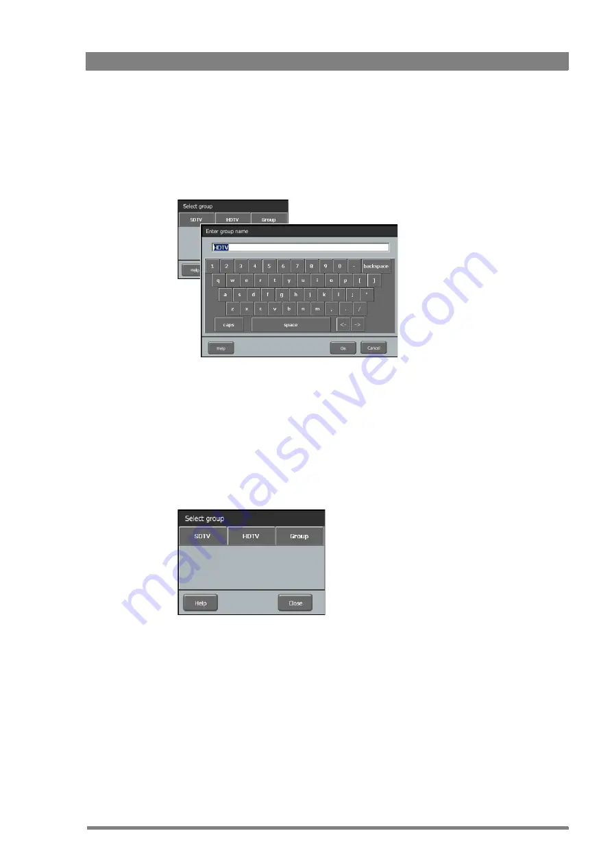
3.5.3  Renaming a group

To change the name of a group within a group click or tap 

Rename Group 

in the 

Options


window and a list of existing groups will be displayed. Click or tap the name of the group you 
want to change and enter a new name in the keyboard window. 

Click or tap 

Ok

 to return to the Options window.

3.5.4  Deleting a group

To delete a group of cameras click or tap 

Delete Group

 in the Options window. A list of groups 

will be displayed. Click or tap the name of the group you want to delete. The group will be 
deleted and the window closes.

Содержание Grass Valley MCP 450

Страница 1: ...3922 496 32291 February 2018 v1 1 Software v1 3 0 0 MCP 450 User s Guide Master Control PC...

Страница 2: ...ty model or design Liable to technical alterations in the course of further development Trademarks Grass Valley MCP Series LDX Series and derivatives are trademarks of Belden Inc or Grass Valley Canad...

Страница 3: ...n 17 2 3 1 Software Version 17 2 3 2 HW Model Name 17 2 3 3 Serial nr 17 2 3 4 PID 17 2 3 5 IP Address 17 Chapter 3 Operation 3 1 Operating a single camera 19 3 1 1 Switching to single camera mode 19...

Страница 4: ...le management 32 3 6 2 Scene files menu 32 3 6 3 Scene file actions 33 3 6 4 Controlling multiple files 35 3 6 5 Editing files 36 3 7 Diagnostics 38 3 7 1 Diagnostics screen 38 3 7 2 Ref Available 38...

Страница 5: ...the containers and materials of the original packaging Attach a tag indicating the type of service required return address model number full serial number and the return number which will be supplied...

Страница 6: ...6 MCP 450 Master Control PC User s Guide v1 1...

Страница 7: ...IP as its communication protocol The MCP 450 not only controls all camera functions it can also be used to change the menu settings of all Grass Valley XCU Base Stations Extensive setup functions for...

Страница 8: ...function provides full overview of all cameras connected to the C2IP network simultaneously and supports the control of multiple cameras at the same time Uses off the shelf IT network infrastructure...

Страница 9: ...twork The IP address and other options for the Ethernet connection can be set up in the MCP setup menu Note Note When an MCP 450 is present in a C2IP network up to three more Operational Control Panel...

Страница 10: ...d their values Main menu selects camera operation mode manages groups of functions manages files Diagnostics provides a quick status overview of the system Call button sends Call signal to camera oper...

Страница 11: ...ctions and their settings Main menu selects camera operation mode manages groups of functions manages files Camera selection displays currently selected camera select a camera define and maintain grou...

Страница 12: ...12 MCP 450 Master Control PC User s Guide v1 1 Chapter 1 Introduction...

Страница 13: ...USB connectors For touchscreen operation Connect the USB touch connection of the monitor to one of the three available USB connectors Connect the Ethernet cable from the camera control C2IP network t...

Страница 14: ...ys starts up after power is connected When Power Off is selected the box computer can be switched on or off by pushing the power switch at the front panel Press F4 to save the configuration and exit s...

Страница 15: ...User s Guide v1 1 15 Chapter 2 Installation Go to the Windows desktop click Start and then click Control Panel In the Control Panel click Network and Sharing Center At the left side of the window clic...

Страница 16: ...own in the list to see all items The Internet Protocol version 4 TCP IPv4 Properties dialog box appears Now you can choose between manual and automatic IP address assignment Click the option button of...

Страница 17: ...roup The MCP setup functions are shown 2 3 1 Software Version Displays the current version of the MCP 450 application software 2 3 2 HW Model Name Displays the hardware model name of the Embedded Box...

Страница 18: ...18 MCP 450 Master Control PC User s Guide v1 1 Chapter 2 Installation...

Страница 19: ...nd three buttons are shown one of which is the Video Adjust button the other two are System and Function Select 3 1 2 Function sets Each of the three buttons selects a set of function groups that are...

Страница 20: ...ear For more information about defining your own set of function groups refer to Selecting functions on page 26 3 1 3 Function field The centre of the screen shows a part of the function field that ho...

Страница 21: ...lues clicking or tapping the value toggles between the two values If there are more than two values a drop down list of values appears Click or tap the value you want in the list If you select an anal...

Страница 22: ...ap Set Active to activate or de activate the selected set 4 Click or tap Color and use the Value Selector at the right to select a color Click or tap Width and use the Value Selector to select an area...

Страница 23: ...ains more functions than will fit on the screen use the round scroll buttons on the top and bottom to scroll through the functions Settings Overview set Contains all main video functions Note that the...

Страница 24: ...amera numbers that are out of view can be accessed by scrolling through the cameras using the scroll buttons at the top 3 2 4 Changing values Click or tap the value displayed next to a switch function...

Страница 25: ...the values in the row this value will become the master value the values of all other cameras will follow its settings Analog functions can be changed using the Rotary Controls at the bottom Select or...

Страница 26: ...opens showing a list of all functions that can be controlled by the MCP 400 Note Note When the function selection window opens the existing selection is discarded Reload your selection by clicking or...

Страница 27: ...mes 3 3 4 Selecting all functions If you want to control all available functions click or tap the All button and the list of function groups will be selected When you are done selecting functions and...

Страница 28: ...our dots light up yellow when the camera has ISO status and they are red when the camera is On Air Note Note When no camera is selected the message select CAM is shown 3 4 2 Selecting a camera in sing...

Страница 29: ...selection window closes or If a group was selected the camera selection window displays all cameras in that group You can make a new selection from the cameras Click or tap Ok to activate this select...

Страница 30: ...tap the OK button to return to the Options window Click or tap Close to return to the camera selection window The new group has been added to the groups list 3 5 2 Editing a group To change the set o...

Страница 31: ...roups will be displayed Click or tap the name of the group you want to change and enter a new name in the keyboard window Click or tap Ok to return to the Options window 3 5 4 Deleting a group To dele...

Страница 32: ...s are reported to have reduced speed performance when used with the MCP 400 When this situation occurs try to use a different capacity or brand of USB Flash Drive To access File Management click or ta...

Страница 33: ...Current settings location Contains the current camera settings represented as a file Its name is copied from the latest recalled or restored scene File Factory standard file location Contains the Fact...

Страница 34: ...e Note The existing file stored in this location will be deleted Save to USB Copies the scene file from this location to the MCP 400 s USB Flash Drive Load from USB Copies the scene file from the MCP...

Страница 35: ...eously select a row of scene file locations at the top of the matrix Click or tap one of the locations to open the action menu Recall and Store are carried out for each selected camera individually Sa...

Страница 36: ...the File Management menu to open a new window At the bottom there are four buttons Load Save As Filter and Close 2 Make sure a USB Flash Drive is inserted into the MCP 400 Click or tap the Load button...

Страница 37: ...p the Filter button to open the Filter Menu Select or unselect functions as described in Selecting functions on page 26 6 Click or tap the Save As button to save your edited scene file to the USB Flas...

Страница 38: ...of the Base Station Can be Yes No Lock or No warning highlight 3 7 4 Camera Comm Shows the communication status between the MCP 400 and the camera Can be Yes or No warning highlight 3 7 5 Basestation...

Страница 39: ...Bs is shown 3 7 9 C BS FibSignal Shows signal quality for Fiber connections from Camera to Base Station 3 7 10 BS C FibCable Shows cable quality for Fiber connections from Base Station to Camera Also...

Страница 40: ...40 MCP 450 Master Control PC User s Guide v1 1 Chapter 3 Operation...

Страница 41: ...C 32 to 104 F Storage temperatures 40 to 85 C 40 to 185 F Power requirements 12 VDC 10 nom 1 5 A Power consumption via power adapter DC 12 V 36 W max Ethernet connection 2 x RJ 45 connector 10 100 100...

Страница 42: ...User s Guide v1 1 Chapter 4 Specifications 4 3 Mounting To mount the MCP 450 in a desk or onto a wall use the supplied mounting kit that suit you mounting situation DIN rail mounting VESA plate mount...

Страница 43: ...MCP 450 Master Control PC User s Guide v1 1 43...

Страница 44: ......

Отзывы: