Operation
It is important that each operator of the Tar River Wood Chipper read and understand the operational pro-
cedures and all related safety precautions outlined in this section. The following preoperation checklist is
provided for the operator. It is important for both the personal safety and maintaining good mechanical
condition that this checklist is followed.
Caution: Always wear personal protective equipment (PPE) whenever operating the machine. This includes but
is not limited to protective shoes with slip resistant soles, protective goggles or face shield, heavy gloves, hearing pro-
tection and protective clothing.
Do not place metal, bottles, cans, rocks, glass or other solid material into the wood chipper. If something like this gets
into the machine, stop the machine immediately for a detailed inspection. Stop engine, remove ignition key and place in
your pocket and wait for all moving parts to stop before inspecting or unplugging. Inspect machine for damaged or
loosened parts before resuming work.
Prior to operating the Wood Chipper:
1. Lubricate the machine per the schedule out-line in the Maintenance Section.
2. Check the rotor, blades and twig-breaker. Remove any twine, wire or other material that has become entangled.
3. Check the condition and clearance of the twig- breaker, rotor and stationary blades. Adjust or replace as required.
4. Check that all bearings turn freely. Replace any that are rough or seized.
5. Make sure that all guards and shields are in place, secured and functioning as designed.
6. Check the condition of the curtain in the feed hopper. It must be in good condition to prevent chips from flying out.
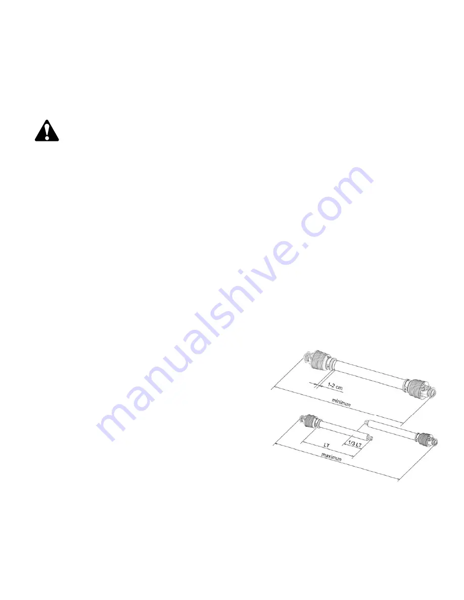
Shortening a PTO Driveline
Depending on our tractor, it may be necessary to cut the PTO drive line that is
supplied with the machine. To accommodate the variety of 3 point hitch
geometry available, the drive line may be too long or too short for the trac-
tor. It is very important that the drive line be free to telescope but not to
bottom out when going through its working range. If the drive line bot-
toms out, the bearings on both the machine and tractor PTO shaft will be
overloaded and fail in a short time.
1.
With the implement attached to the tractor’s three point hitch, and the
PTO driveline not installed, separate the PTO driveline. Attach the im-
plement end to the implement and the other end to the tractor PTO input
shaft.
2.
Raise the implement by using the tractor’s hydraulic 3-point hitch to it’s
maximum lift height.
3.
Hold the half shafts next to each other and mark them so each end is approximately ½” from hitting the end of the telescopic
profiles.
4.
Shorten the inner and out guard tubes equally.
5.
Shorten the inner and outer profiles by the same length as the guard tubes. Using a rattail file, round off all sharp edges and
burrs. Grease the telescopic profile generously before reassembling.
9


