1523.5-0000010 OM
149
5.4.2.3 Operation 19. Washing of the tractor and cleaning of the cabin interiors
Wash the tractor and clean the cabin inside.
Before washing the tractor with water jet, stop the engine, put the battery disconnect
switch in “OFF” position.
While tractor washing, it is necessary to take steps to protect electric and electronic com-
ponents, plugs and sockets against entry of water jets. It is forbidden to direct water jet on-
to electric and electronic work-pieces and cable connectors.
Maximum water temperature shall not exceed 50
0
С
. It is forbidden to add corrosive agents
(detergents) into water for washing.
After tractor washing, clean the electric and electronic work-pieces and cable con-
nectors with compressed air.
5.4.2.4 Operation 20. Check of bolt tightening of CAC air duct clamps
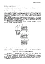
Check and if necessary, tighten clamp bolts 3 (figure 5.4.9) of CAC air ducts. Bolt
torque of worm type clamps shall be from 5 to 8 Nm, bolt torque of hinge type clamps –
from 10 to 15 Nm.
ATTENTION: AFTER CHECK OF CLAMP BOLTS TIGHTENING TORQUE, IT IS RE-
QUIRED TO CHECK HERMITICITY OF ALL JOINTS OF CAC DUCT. TO DO THIS, IN-
SPECT THE JOINTS OF ALL AIR PIPELINES AND SILICONE CONNECTING PIPES OF
THE CAC SYSTEM FOR DAMAGES AND LEAKAGES. IN CASE OF DETECTION ANY
FAILURES AND DAMAGES, IT IS REQUIRED TO FIND OUT THE REASON FOR THEIR
APPEARANCE AND TAKE MEASURES TO ELIMINATE THEM!
IT IS FORBIDDEN TO OPERATE THE TRACTOR WITH THE CAC SYSTEM FAULTY!
5.4.2.5 Operation 21. Check of pneumatic pressure in tires
Value pressure in front and rear tires shall be chosen according to the load per single tire,
driving speed and operations performed. If it is necessary, bring tire pressure to the re-
quired value according to subsection 3.2.8 “Selection of optimal internal pressure in tires,
depending on operating conditions and load on tractor axles”.
ATTENTION: CONTROL AND BRINGING TIRE INTERNAL PRESSURE TO THE NOR-
MAL VALUE, WHEN NEEDED, SHALL BE CARRIED OUT EACH TIME THE TRACTOR
CHANGES ONE OPERATION TO ANOTHER AND CHANGES IMPLEMENTS AND MA-
CHINES COUPLED!
5.4.2.6 Operation 22. Drainage of sediment from the fuel tank
To drain sediment from the fuel tank, it is necessary to do the following:
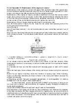
- screw out tank adapter 1 with screw key S 17 (figure 5.4.11, tank adapter 1 is lo-
cated at the bottom of fuel tank 2);
- drain sediment until clean fuel appears;
- after clean fuel without water and dirt appears, screw in tank adapter 1, holding
metallic embedded part of fuel tank 2.
1 – adapter; 2 – fuel tank.
Figure 5.4.11 – Drainage of sediment from the fuel tank


