background image

4


INSTALLATION INSTRUCTION 


Asia-Pacific 

+86 755 298 85888


Europe, Middle East 

+353 61 225 977


North America 

+1


408


785 5200


© 2020 Bel Power Solutions & Protection


BCM.00428_AC


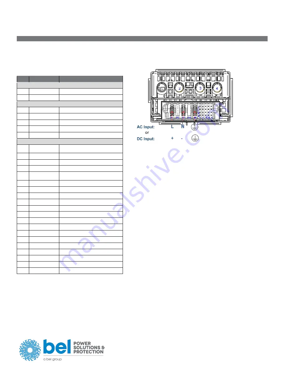
PIN ALLOCATION


Unit:   


FCI Connectors P/N 51939-768LF Note: A1 and A2 are Trailing Pin (short pins)  

Counterpart:   

FCI Connectors P/N 51915-401LF  


For Main Output Pins, see section 15 of Datasheet BCD.00833  


PIN  

NAME  

DESCRIPTION  

Output  


3,4  

V1  

+12 VDC main output  

1,2  

PGND  

+12 VDC main output ground  

Input Pins  


P1  

LIVE  

AC Live Pin / Positive  

P2  

N.C  

No metal pin connection  

P3  

NEUTRAL  

AC Neutral Pin / Negative  

P4  

N.C.  

No metal pin connection  

P5  

P.E.  

Protective Earth Pin  

Control Pins  


A1  

PSKILL  

Power supply kill (trailing pin): active-
low  

B1  

PWOK_L  

Power OK signal output: active-low  

C1  

INOK_L  

Input OK signal: active-low  

D1  

PSON_L  

Power supply on input: active-low  

A2  

PRESENT_L  

Power supply present (trailing pin): 

active-low  

B2  

SGND  

Signal ground

1)

 (return)  

C2  

SGND  

Signal ground

1) 

(return)  

D2  

SGND  

Signal ground

1)

 (return)  

A3  

SCL  

I2C clock signal line  

B3  

SDA  

I2C data signal line  

C3  

SMB_ALERT_L  

SMB Alert signal output: active-high  

D3  

ISHARE  

V1 Current share bus  

A4  

EEPROM_WP  

EEPROM write protect  

B4  

RESERVED  

Reserved  

C4  

V1_SENSE_R  

Main output negative sense  

D4  

V1_SENSE  

Main output positive sense  

A5  

VSB  

Standby positive output  

B5  

VSB  

Standby positive output  

C5  

VSB_GND  

Standby Ground

1)


D5  

VSB_GND  

Standby Ground

1)


1)

 These pins should be connected to PGND on the system.  


Содержание TET3000-12-069RA

Страница 1: ...m Abkühlen des Gerätes bevor Sie es berühren Lassen Sie keine Flüssigkeiten oder Fremdkörper in die Geräte eindringen Um Überschläge zu vermeiden schließen Sie das Gerät nicht an oder trennen Sie es nicht ohne vorher die Eingangsspannung abgeschaltet zu haben und warten Sie die Entladung der internen Kondensatoren ab mindestens 2 Minuten RISCHIO USTIONI ESPLOSIONE INCENDIO SCOSSA LESIONI GRAVI Non...

Страница 2: ...ION Ambient Temperature Range 40 C to 60 C See output table for details Relative Humidity Range 7 to 93 RH Non Condensing Altitude 0 to 2000 meters ASL at 0 C to 50 C TET3000 12 069RA 0 to 2000 meters ASL at 0 C to 45 C TET3200 12 069RA 0 to 5000 meters ASL at 0 C to 40 C SAFETY APPROVALS Approved to the latest version of the following safety standards UL CSA 62368 1 IEC EN 62368 1 and IEC EN 6095...

Страница 3: ... 603 7 20 15 20 35 AIRFLOW DIRECTION LED INDICATORS OPERATING CONDITION LED SIGNALING AC LED AC Line within range Solid Green AC Line UV condition Off LED Normal Operation Solid Green PSON_L High Blinking Yellow 1 1 V1 or VSB out of regulation Solid Yellow Over temperature shutdown Output over voltage shutdown V1 or VSB Output under voltage shutdown V1 or VSB Output over current shutdown V1 or VSB...

Страница 4: ...rotective Earth Pin Control Pins A1 PSKILL Power supply kill trailing pin active low B1 PWOK_L Power OK signal output active low C1 INOK_L Input OK signal active low D1 PSON_L Power supply on input active low A2 PRESENT_L Power supply present trailing pin active low B2 SGND Signal ground1 return C2 SGND Signal ground1 return D2 SGND Signal ground1 return A3 SCL I2C clock signal line B3 SDA I2C dat...

Отзывы: