


PRESET RESISTORS
CPU PRINTED CIRCUIT BOARD
RVI - Liquid crystal display contrast - set for maximum readability.
ADAREF PRINTED CIRCUIT BOARD (INPUT/OUTPUT GAIN SET)
With +6db measured at the input (analog) XLR connectors (single ended), the
sensitivity control on the front panel set to Max, and the output connectors single ended
with 600½ loads:-
Adjust RV8 for +9dB at TP9 (right channel)
Adjust RV9 for +9dB at TP10 (left channel)
Adjust RV3 for +12dB at TP3 (right channel)
Adjust RV4 for +12dB at TP4 (left channel)
Set the Bel 6110 into ÒfollowÓ mode and connect valid timecode to SMPTE input, and
press ÒrecordÓ switch.
Record for full memory and stop.
Press Play Switch and:-
Adjust RV5 for +17dB across Right output connector (across 600½ load).
Adjust RV6 for +17dB across Left output connector (across 600½ load).
Set sensitivity control on the front panel for +6dB across 600½ loads on the output
connectors and check for channel balance. Trim RV8 and RV9 as necessary.
Check for +6dB across 600½ loads on the output connectors when in ÒrecordÓ (E-E)
and channel balance. Trim RV3 or RV4 if necessary.
PRESET CAPACITORS
ADAREF PRINTED CIRCUIT BOARD
Please capacitor C82 adjustment (video PLL lock).
With digital AES reference set to ÒVideoÓ and any external AES digital ÒVideoÓ
reference disconnected, monitor the AES digital output for ÒSample FrequencyÓ.
Adjust C82 if necessary to give sample frequency within ±25ppm of 48kH±(Fs).
Connect a suitable external (AES digital) video reference and check that a ÒlockÓ is
achieved.
27
A/D input levels set
E - E set
Содержание 6110
Страница 7: ...DIAGRAM 1 SET UP MENUS 7 ...
Страница 8: ...DIAGRAM 2 SET UP MENUS 8 ...
Страница 17: ...DETAIL OF SWITCHES ON FRONT DEFAULT LCD REAR PANEL VIEW 17 Figure 2 Figure 3 Figure 4 ...
Страница 19: ...REAR PANEL LAYOUT 19 ...
Страница 20: ...BLOCK DIAGRAM 20 ...
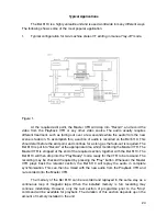
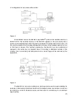
Страница 22: ...BEL 6110 Lay off recorder Application Notes 22 ...