


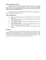


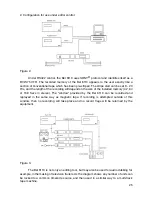


CONNECTIONS
The rear panel has twelve connectors, a voltage selector and a combined IEC power
inlet switch and fuseholder. From left to right these are:-
Switch, Fuse, IEC 3 pin power inlet (combined EMI filter unit)
Mains power voltage selector (115V / 230V)
RS422 Serial Port 9-pin female miniature D-type (lockable)
Remote Control 9-pin female miniature D-type (lockable)
Time-Code Input 3-pin XLR type connector (female) for SMPTE input Balanced
Digital Ref: Word 50½ BNC (4k7½)
Digital Ref: Video 75½ BNC medium impedance (75½ termination link internal)
Digital Output (AES/EBU) male XLR 3-pin (110½)
Digital Input (AES/EBU) female XLR 3-pin (110½)
Digital Ref: AES (48kHz) female XLR 3-pin (110½)
Left and Right Audio Outputs 3-pin XLR type connector (male). Balanced Pin 2 hot.
Left and Right Audio Inputs 3-pin XLR type connectors (female). Balanced Pin 2 hot.
EMC COMPLIANCE
The BEL 6110 was designed and tested to comply with the EMC directive numbers
EN55103, EN55022, EN55082-1 and EN60950 when used as directed.
This unit must be used with an earthed mains lead to comply with the CE low voltage
directive.
CE
12
Содержание 6110
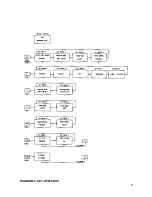
Страница 7: ...DIAGRAM 1 SET UP MENUS 7 ...
Страница 8: ...DIAGRAM 2 SET UP MENUS 8 ...
Страница 17: ...DETAIL OF SWITCHES ON FRONT DEFAULT LCD REAR PANEL VIEW 17 Figure 2 Figure 3 Figure 4 ...
Страница 19: ...REAR PANEL LAYOUT 19 ...
Страница 20: ...BLOCK DIAGRAM 20 ...
Страница 22: ...BEL 6110 Lay off recorder Application Notes 22 ...