19
Annunciators above the digital display show the
status of both alarms, and the digital display can
be
programmed
to
alternate
between
the
measured value and an alarm identification.
Programmable functions for each alarm include
adjustable setpoint, hysteresis, alarm delay and
alarm accept.
When frequent setpoint changes
are required, a separate menu provides direct
access to both setpoints from the display mode
without giving the operator access to the
programme and alarm menus. A different security
code may be included to prevent tampering or
accidental adjustment.
8.2.1
Solid state output
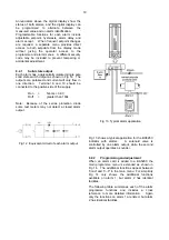
Each alarm has a galvanically isolated single pole
solid state switch output as shown in Fig 12. The
outputs are polarised and current will only flow in
one direction.
Terminal 8 and 10 should be
connected to the positive side of the supply.
Ron
=
5ohms + 0.6V
Roff
=
greater than 180k
Note: Because of the series protection diode
some test meters may not detect a closed alarm
output.
Fig 12 Equivalent circuit of each alarm output
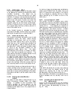
Fig 13 Typical alarm application
Fig 13 shows a typical application for the BA526C
indicator with alarms.
A solenoid valve is
controlled by one alarm output, while the second
alarm output operates a sounder.
8.2.2
Programming and adjustment
When an alarm card is added to a BA526C the
main programme menu is extended as shown in
Fig 14. The additional functions appear between
'Cond' and 'C--P' in the main menu. For simplicity
Fig 14 only shows the additional functions
available on alarm 1, but alarm 2 has identical
facilities.
The following table summaries each of the alarm
programme functions and includes a cross
reference to more detailed information.
Again
only the functions on alarm 1 are listed, but alarm
2 has identical facilities
Содержание BA526C
Страница 11: ...11 ...


