


6
5.1.1 With Zener barriers
There are three requirements when designing a
BA474D loop using Zener barrier(s):
1.
The intrinsic safety output parameters of the
Zener barrier must be equal to or less than:
Uo
=
28V
Io
=
200mA
Po =
0.85W
2. The voltage between terminal 5 & 6 of the
BA474D must be between 9 & 28V.
Note:
Zener barriers are not normally able to
power a BA474D transmitter fitted with an
optional display backlight which requires a
minimum of 15.5V between terminals 5 & 6.
3. The maximum supply voltage must not
exceed the maximum working voltage of the
Zener barrier(s).
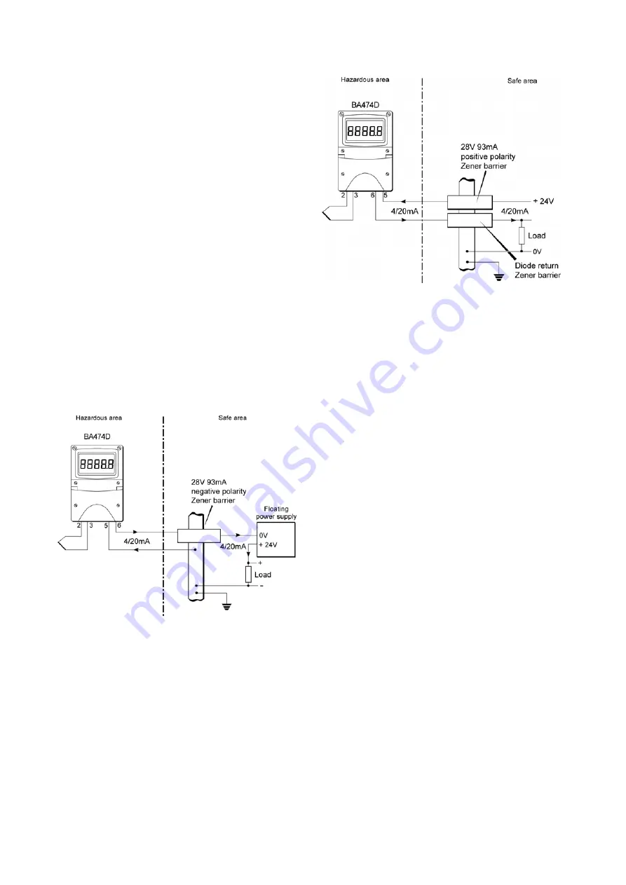
Fig 2 illustrates the simplest and least expensive
configuration in which a BA474D is powered from an
isolated (floating) power supply. Only one barrier is
required, as the other wire is earthed at the barrier
busbar.
Fig 2 BA474D powered from floating supply
If a common power supply is used to operate multiple
loops, the negative side of the supply is normally
earthed. To also allow the negative side of the
4/20mA load to be earthed it is necessary to have a
Zener barrier in each of the two wires entering the
hazardous area as shown in Fig 3.
Fig 3 BA474D powered from a common supply
When designing a transmitter loop it is necessary to
establish that the sum of the voltage drops caused by
the transmitter, Zener barriers, the load and the cable
resistance is less than the minimum supply voltage.
For the transmitter loop shown in Fig.3
Minimum operating voltage of BA474D
9.0V
without optional backlight.
Maximum voltage drop caused by 28V
6.8V
93mA Zener barrier.
(340
Ω
x 20mA)
Maximum voltage drop caused by
1.6V
diode return Zener barrier.
Maximum voltage drop caused by
5.0V
250
Ω
load.
(250
Ω
x 20mA)
Maximum voltage drop caused by
0.2V
cable resistance.
(10
Ω
x 20mA)
______
Total maximum voltage drop
22.6V
The power supply voltage must therefore be above
22.6V but below the maximum working voltage of the
28V 93mA barrier which is likely to be about 26.5V.


