6. CONFIGURATION AND CALIBRATION
The BA354E is configured and calibrated via four
push buttons that are located behind the
instrument control cover. If frequent access to
the push buttons is required, the Rate Totaliser can
be supplied with duplicate membrane keypad
mounted on the outside of the control cover.
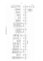
All the configuration functions are contained in an
easy to use menu that is shown diagrammatically
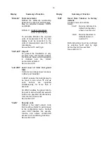
in Fig 7. Each function is summarised in section
6.3 which includes references to more detailed
information. Although this simple menu driven
system enables most adjustments to be made
without repeated reference to this manual, it is
recommended that at least the summary of the
configurable functions in section 6.3 is read before
attempting configuration or recalibration.
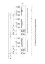
When the instrument is fitted with alarms, the basic
menu is expanded to include the alarm functions
that are described in section 10.2 of this manual.
Note:
While the instrument is being configured or
calibrated totalisation is suspended, any flow
occurring during this time will not be
recorded.
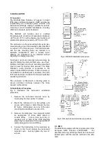
6.1 Calibration structure
Fig 6 shows the BA354E calibration structure. The
4/20mA input current, which in flow applications
represents flow rate, is usually displayed on the
five digit plus sign lower display. If necessary this
flow signal may be linearised using the square root
extractor or the 16 segment lineariser which are
selectable in the instrument’s ‘FunC’ sub-menu.
The rate display may then be calibrated using the
'CAL' or '5Et' functions to show the flow rate in the
required linear engineering units. Both the zero
(display at 4mA) and the span (display at 20mA)
are adjustable, although for unidirectional flow
application the display at 4mA is usually zero.
The position of the decimal point in the rate display
is defined by the ‘dP’ function. To simplify
calibration the BA354E uses floating point
arithmetic, moving the rate display decimal point
position will therefore affect totalisation.
For bi-directional flow applications zero flow will be
represented by an input current other than 4mA.
When one of the two bi-direction functions in the
‘FunC’ sub-menu is selected, input currents below
that representing zero flow will be shown as a
negative flow rate and the total flow display will
count down. For input currents above that
representing zero flow will be shown as a positive
flow rate and the total flow display will count up.
Fig 6 Calibration structure
The BA354E total display is calculated from the
rate display using two serial factors: the timebase
't-bA5E' and the total scaling factor '5CALE-t'. The
timebase divides the rate display according to
whether the rate display represents flow per
second, per minute or per hour. The total scaling
factor '5CALE-t' is a wide range configurable
dividing factor allowing the rate and total displays
to be in different units.
10
Содержание BA354E
Страница 14: ...14 ...
Страница 21: ...21 ...
Страница 30: ...30 ...
Страница 40: ...40 ...
Страница 41: ...41 ...
Страница 42: ...42 ...
Страница 43: ...43 ...
Страница 44: ...44 ...
Страница 45: ...45 ...
Страница 46: ...46 ...
Страница 47: ...47 ...
Страница 48: ...48 ...
Страница 49: ...49 ...
Страница 50: ...50 ...


