background image

18

9.  ACCESSORIES

9.1 External keypad

The four indicator push buttons are located behind
the  instrument  control  cover,  for  applications
requiring  frequent  adjustment  an  optional  control
cover fitted with an external keypad is available.
This  keypad  maintains  the  enclosure  ingress
protection  and  accidental  push  button  activation
can  be  prevented  by  use  of  a  menu  security
access code, see section 6.10.

9.2 Units measurement & instrument

identification.

Both the BA304E and the BA324E indicators are
fitted  with  a  blank  escutcheon  around  the  liquid
crystal display.  This can be supplied printed with
any  units  of  measurement  and  tag  information
specified at the time of ordering.  Alternatively, the
information may be added on-site via an embossed
strip, dry transfer or a permanent marker.  

To  gain  access  to  the  display  label  remove  the
terminal cover by unscrewing the two 'A' screws
which will reveal two concealed 'D' screws.   If the
instrument  is  fitted  with  external  keypad,  also
unscrew the two 'C' screws securing the buttons
and  un-plug  the  five  way  connector.    Finally
unscrew all four 'D' screws and carefully lift off the
front of the  instrument.     The location  of all  the
screws is shown in Fig 4. 

Add the required legend to the display escutcheon,
or  stick  a  new  pre-printed  self-adhesive
escutcheon,  which  is  available  from  BEKA
associates, on top of the existing escutcheon.  Do
not remove the original escutcheon.

Both indicators can also be supplied with a blank
or  custom  laser  engraved  stainless  steel  plate
secured  by  two  screws  to  the  front  of  the
instrument  enclosure.  This  plate  can
accommodate:

      1 row of 9 alphanumeric characters 10mm high

  or 1 row of 11 alphanumeric characters 7mm high

  or 2 rows of 18 alphanumeric characters 5mm high

9.3  Alarms

CAUTION

These alarms outputs should not be used for
critical  safety  applications  such  as  an
emergency shut down system.

Both  models  can  be  supplied  with  factory  fitted
dual solid state, single pole alarm outputs.   Each
alarm output may be independently conditioned as
a  high  or  low  alarm  with  a  normally  open  or
normally closed output in the non-alarm condition.  

When the 4/20mA current powering the indicator is
removed both alarm outputs will open irrespective
of configuration.  The open circuit condition should
therefore be chosen as the alarm condition when
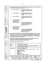
designing an alarm system.    Fig 9 illustrates the
conditions available and shows which are fail safe. 

When  an  alarm  occurs  an  alarm  annunciator  on
the indicator front panel is activated and if required
the  numerical  display  can  alternate  between  the
measured  value  and  the  alarm  channel
identification ‘ALr1’ or ‘ALr2’.

CAUTION

The  alarms  are  activated  by  the  indicator’s
numerical display.  Use of the Tare Function
‘tArE’ will change the numerical display, the
alarms will continue to function at the original
displayed value, but this will correspond to a
different input current.

Fig 9  Alarm outputs

Configurable  functions  for  each  alarm  include
adjustable  setpoint,  hysteresis,  alarm  delay  and
alarm accept.

Содержание BA304E

Страница 1: ...Issue 8 5th May 2016 BA304E BA324E intrinsically safe loop powered field mounting indicators Issue 8 ...

Страница 2: ...eariser error message 7 4 Lineariser default configuration 8 Maintenance 8 1 Fault finding during commissioning 8 2 Fault finding after commissioning 8 3 Servicing 8 4 Routine maintenance 8 5 Guarantee 8 6 Customer comments 9 Accessories 9 1 External keypad 9 2 Units of measurement and instrument identification 9 3 Alarms 9 3 1 Solid state output 9 3 2 Intrinsic safety 9 3 3 Configuration and adju...

Страница 3: ...Type Examination certificate specifies that under fault conditions the output voltage current and power at the 4 20mA input terminals will not exceed those specified for simple apparatus in Clause 5 7 of EN 60079 11 which simplifies installation and documentation For international applications both models have IECEx certification which is described in Appendix 2 For installations in the USA and Ca...

Страница 4: ...ation ATEX dust and IECEx approvals are described in Appendixes 1and 2 3 1 ATEX gas certification Notified Body Intertek Testing and Certification Ltd have issued both models with a common EC Type Examination Certificate number ITS11ATEX27253X This confirms compliance with harmonised European standards and it has been used to confirm compliance with the European ATEX Directive for Group II Categor...

Страница 5: ... ATEX certification information and BEKA associates name and location Non European certification information may also be shown The instrument serial number and date of manufacturer are recorded on a separate label inside the terminal compartment BA304E certification label BA324E certification label 4 SYSTEM DESIGN FOR GAS HAZARDOUS AREAS 4 1 Transmitter loops Both models may be connected in series...

Страница 6: ...he indicator plus the interface When a high integrity earth connection is already available a Zener barrier is usually the least expensive option If an earth connection is not available or isolation is required a galvanic isolator is the correct choice If one side of the 4 20mA current loop may be earthed a single channel Zener barrier provides the lowest cost protection If the 4 20mA signal is no...

Страница 7: ...thed post or structure the earth terminal should be connected to the plant potential equalising conductor The enclosures are fitted with a bonding plate to ensure electrical continuity between the three conduit cable entries 5 2 Installation Procedure Fig 4 illustrates the instrument installation procedure a Remove the instrument terminal cover by unscrewing the two captive A screws b Mount the in...

Страница 8: ...ation Default Configuration BA304E BA324E Access code CodE 0000 0000 Function FunC Linear Linear Display at 4mA Zero 0 0 0 00 Display at 20mA SPAn 100 0 100 00 Resolution rESn 1 digit 1 digit Bargraph start BarLo 0 00 Bargraph finish BarHi 100 00 P button in display mode C P Tare tArE Off Off 6 1 Summary of configuration functions This section summarises each of the main configuration functions an...

Страница 9: ...9 ...

Страница 10: ...Lin 16 segment adjustable lineariser To reveal the existing indicator function select FunC from the configuration menu and press P If the function is set as required press E to return to the menu or press the or button to change the setting followed by the E button to return to the configuration menu Std Linear Provides a linear relationship between the 4 20mA indicator input current and the indic...

Страница 11: ...between the two currents is greater than 4mA If these conditions are not complied with the indicator displays FaiL and aborts the calibration c If the zero current is greater than the span current the instrument will be reverse acting i e an increasing input current will cause the display to decrease 6 6 Calibration using internal reference SEt Using the SEt function the indicator can be calibrate...

Страница 12: ...setting between on and oFF When set as required press E to return to the tARE prompt in the configuration menu 6 10 Security code CodE Access to the instrument configuration menu may be protected by a four digit security code which must be entered to gain access New instruments are configured with the default security code 0000 which allows unrestricted access to all configuration functions To ent...

Страница 13: ...direct calibration of the lineariser with an external current source and is the preferred method when traceability is required If the exact system non linearity is unknown this method also allows direct calibration from the variable to be displayed e g the output from a level sensor in an irregular tank may be displayed in linear volumetric units by filling the tank with known incremental volumes ...

Страница 14: ...14 ...

Страница 15: ...ollowing break point 7 1 1 Example Adding break points to a new indicator When adding break points to a new indicator or to a lineariser following resetting to the factory defaults using the LtAb function described in section 6 11 each additional break point should be added before the highest existing breakpoint The first additional break point should be added before the default break point 1 1 wh...

Страница 16: ...nction by pressing the E button The corresponding indicator display at each of the break points can now be defined using the diSP sub function Using the and buttons select the diSP sub function and press P which will reveal the starting point for the first break point 0 n where n is the total number of break points entered Press P and use the and buttons and the P button to move between digits to ...

Страница 17: ... indicator fails after it has been functioning correctly follow the procedure shown in section 8 1 If this does not reveal the cause of the fault it is recommended that the instrument is replaced This can be done without disconnecting power but while the indicator is disconnected the 4 20mA loop will be open circuit 8 3 Servicing All BA304E and BA324E loop powered indicators are interchangeable if...

Страница 18: ...on Both indicators can also be supplied with a blank or custom laser engraved stainless steel plate secured by two screws to the front of the instrument enclosure This plate can accommodate 1 row of 9 alphanumeric characters 10mm high or 1 row of 11 alphanumeric characters 7mm high or 2 rows of 18 alphanumeric characters 5mm high 9 3 Alarms CAUTION These alarms outputs should not be used for criti...

Страница 19: ...ied by clause 5 7 of EN 60079 11 for simple apparatus This simplifies system documentation and allows the alarm output terminals 8 9 and 10 11 to be connected to almost any intrinsically safe circuit protected by a Zener barrier or galvanic isolator providing the output parameters of the circuit do not exceed Uo 30V dc Io 200mA Po 0 84W The maximum equivalent capacitance and inductance between eac...

Страница 20: ...20 ...

Страница 21: ...setpoint The alarm is activated when the indicator display equals the setpoint See section 9 3 5 Hi Lo Alarm function Defines the alarm function as High or Low See section 9 3 6 no nC Normally open or normally closed output Sets the alarm output open or closed in the non alarm condition See section 9 3 7 HStr Hysteresis Adjusts the alarm hysteresis See section 9 3 8 dELA Alarm delay time Introduce...

Страница 22: ...or fail safe operation both alarm outputs should be conditioned to be open in the alarm condition nC To check or change the alarm output status select no nC from the alarm configuration menu and press P to reveal the setting The function may be changed by pressing the or button followed by the E button to return to the alarm configuration menu 9 3 8 Hysteresis HStr Hysteresis is shown in the units...

Страница 23: ...aving access to the indicator configuration menu Protection against accidental adjustment of the setpoints when the indicator is in the display mode is provided by a separate security code This direct setpoint access menu is enabled and the separate security code entered from the ACSP function in the alarm configuration menu as shown in Fig 12 To change the menu parameters select ACSP from the con...

Страница 24: ...oint plus the displayed value to be represented or a low and a high setpoint plus the displayed value to be represented by the bargraph as shown in Fig 14 Fig 14 Displayed value and setpoints on bargraph The bargraph area below the low alarm setpoint and the area above the high alarm setpoint are activated The displayed variable is represented by an activated bar which moves between these low and ...

Страница 25: ...those specified by clause 5 7 of EN 60079 11 for simple apparatus which simplifies system design and documentation Providing the increased voltage drop can be tolerated the intrinsic safety and system design described in sections 3 and 4 of this manual remain valid with the backlight loop powered 9 4 2 Separately powering the backlight The optional backlight may also be powered from a separate saf...

Страница 26: ...al pipe BA392D Stainless steel bracket secured by two worm drive hose clips Will clamp to any vertical or horizontal pipe with an outside diameter between 60 and 80mm BA393 Heavy duty stainless steel bracket secured by a single V bolt Will clamp to any vertical or horizontal pipe with an outside diameter between 40 and 80mm ...

Страница 27: ... in normal operation but if it does occur will only persist for a short period Be used with dust in subdivisions IIIA combustible flyings IIIB non conductive dust IIIC conductive dust Having a Minimum Ignition Temperature of Dust cloud 120 C Dust layer on indicator 155 C up to 5mm thick Dust layer on indicator Refer to over 5mm thick EN 61241 14 At an ambient temperature between 40 and 70 C A1 2 C...

Страница 28: ... apply when the indicator is installed in Zone 1 or in Zone 2 The specified IECEx gas and dust intrinsic safety parameters are identical to the ATEX safety parameters described in the main section and Appendix 1 of this manual The IECEx certificate may be downloaded from www beka co uk www iecex com or requested from the BEKA sales office A2 2 Installation The IECEx and ATEX certificates specify i...

Страница 29: ...rinsically Safe Systems for Hazardous Classified Locations and with the National Electrical Code ANSI NFPA70 Installations in Canada must comply with the Canadian Electrical Code C22 2 The BA304E and BA324E have T5 rating at ambient temperatures up to 70ºC and may be used with the following gases and dusts Intrinsic Safety Division 1 or 2 Class I Group A B Group C Group D Class II Group E F G Clas...

Страница 30: ...30 ...

Страница 31: ...31 ...

Страница 32: ...32 ...

Страница 33: ...33 ...

Страница 34: ...34 ...

Страница 35: ...35 ...

Страница 36: ...36 ...

Страница 37: ...37 ...

Страница 38: ...38 ...

Страница 39: ...39 ...

Страница 40: ...40 ...

Отзывы: