9
SUPER-X PRO CX2310
3. APPLICATIONS
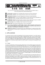
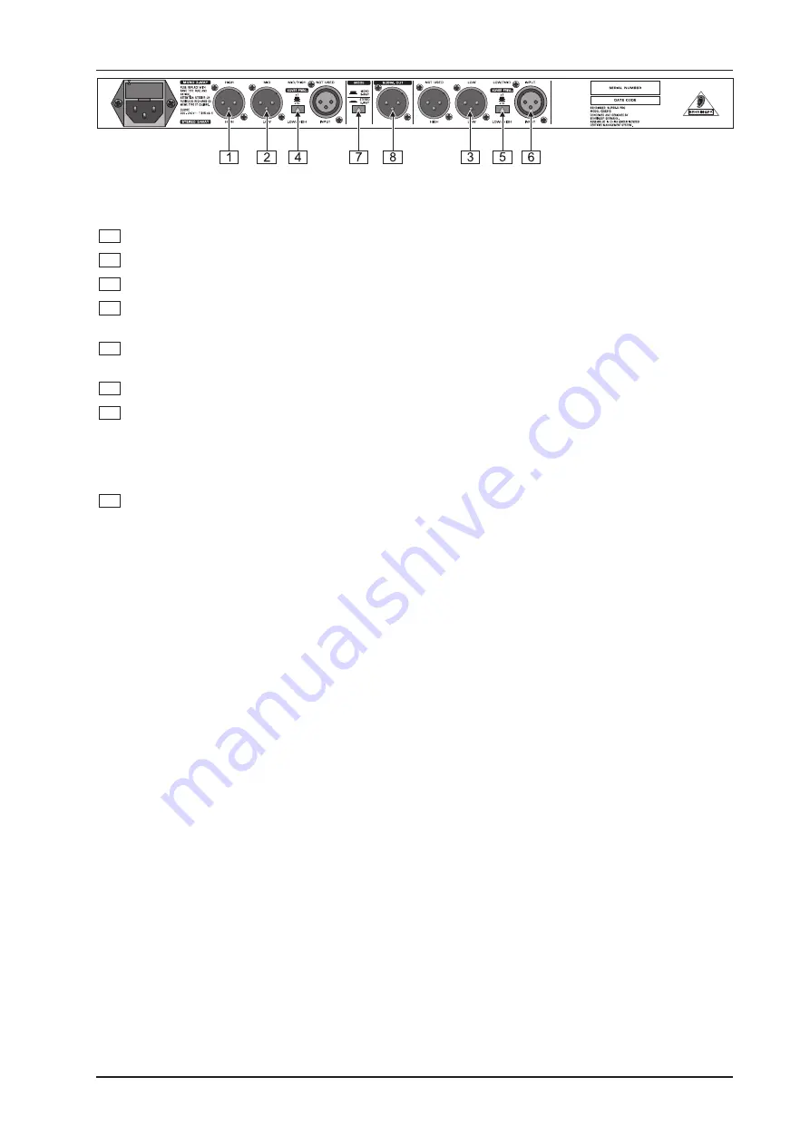
Fig. 2.4: Active control elements and connections on the rear panel of the SUPER-X PRO in
mono 3-way operation with separate subwoofer signal
1
HIGH OUTPUT connector.
This is the balanced XLR connector for the high output signal.
2
MID OUTPUT connector.
This is the balanced XLR connector for the mid output signal.
3
LOW OUTPUT connector.
This is the balanced XLR connector for the low output signal.
4
XOVER FREQ. switch.
This is used to switch between the control ranges of the front panel MID/HIGH
XOVER FREQ. control. The range is either 44 to 930 Hz or 440 Hz to 9.3 kHz.
5
XOVER FREQ. switch.
This is used to switch between the control ranges of the front panel LOW/MID
XOVER FREQ. control. The range is either 44 to 930 Hz or 440 Hz to 9.3 kHz.
6
INPUT connector.
This is the balanced XLR connector for the input signal.
7
MODE switch.
This must be de-activated when in mono 3-way operation.
+
Never activate the MODE and XOVER FREQ. switches without having first switched off the
equipment. Switching between these whilst the equipment is in use produces heavy interference
noise which could damage the loudspeakers or the system.
8
SUBW. OUT connector.
This is the output for the mono subwoofer signal. This signal remains constant
in mono and stereo mode and offers an additional way of providing 2-way and 3-way operation (see
chapter 3.5).
3. APPLICATIONS
You will need some tools to help set up the SUPER-X PRO to its optimal configuration. To set up the crossover
frequency you need to know which frequency range a loudspeaker stack covers, over which range the sound
energy is linearly transmitted, and where reductions or increases in the frequency response occur. In addition,
every room has different size and quality characteristics. These strongly influence the sound response, since
resonances and reflections in the different frequency ranges can also lead to reductions or increases in the
sound picture. You will need suitable equipment in order to be able to recognize and compensate for these
features.
3.1 Tools
You will need a high-grade microphone for making measurements. This should have a frequency response that
should be as linear as possible (e.g. the BEHRINGER measurement microphone ECM8000) and at least linear
over the range from 90 Hz and 15 kHz. Place the microphone about 5 m. in front of the speaker system and
between the diaphragms of the two frequency bands you wish to measure. When using a measuring microphone
to set the levels for the individual frequency bands and the crossover frequencies, you should only operate one
loudspeaker stack. For optimal settings you will usually need to reposition the microphone between two
successive measurements. When used in combination with a measuring microphone and a generator producing
pink noise via an input into the P.A. mixing console, an analyzer will show the sound energy distribution over
the individual frequency bands (usually in 1/3 of an octave). The BEHRINGER ULTRA-CURVE PRO DSP8024
equalizer/analyzer is the ideal tool for this application.
When listening to the overall sound of your system, you should walk around in the audience area and try to
detect resonance frequencies or cancellations. The sound should be optimized for the position where most of
the audience will be gathered, without however neglecting other areas. This often means that the system must
be operated in mono. Whenever you use technical aids such as analyzers, measuring microphones, etc., you
should check the desired results with your own ears.

