


12
BL3300 SERIES MANUAL 01/28/2013
SECTION 3
OPERATION
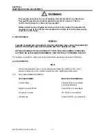
!
WARNING
This equipment involves the use of voltages and currents that can be hazardous. Only qualified
personnel should be allowed to operate or service it. The top cover(s) must always be in place
during operation.
3.1
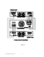
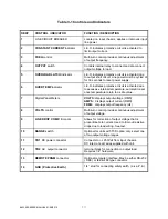
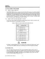
CONTROLS AND INDICATORS
Table 1 lists the controls and indicators used on the different models of the AC Source. The table also
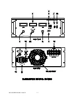
includes their function. Figure 3-1 locates these front panel controls and indicators. Also shown are
the rear panel REMOTE PRGM connector, two terminal strips, cooling fan, and a GND stud.
3.2
TO OPERATE THE EQUIPMENT
1)
Ensure that line circuit breaker and OUTPUT switch are set to OFF.
2)
Connect suitable load across output terminals. (Do not exceed rating of unit.)
3)
Set line circuit breaker of power chassis to ON (cooling fan noise should become evident).
4)
Rotate VOLTS control to desired voltage. ( for T3D units, set the range switch as required ).
5)
Rotate FREQ control to desired frequency.
6)
Set OUTPUT switch to ON to energize load.
NOTE
It is permissible to energize a load gradually by setting the OUTPUT
switch ON and rotating the VOLTS control from zero or a low voltage
position up to the voltage desired.
3.3
SHUTDOWN PROCEDURE
1)
Set OUTPUT switch to OFF.
2)
Set VOLTS control fully counter- clockwise.
3)
Set the line circuit breaker to OFF.
NOTE: once turned off, a period of 30 seconds is required to
reset the soft start circuit. Failure to do so may blow input fuses due to high in-rush current
when power is reapplied.
3.4
ADJUSTMENT OF LINE DROP COMPENSATION AND PHASE ANGLES
The BL series of power supplies provide a means to compensate for load related effects and a means
to trim the phase angles. A “Line Drop Comp” trim is provided for each phase. Phase trim pots are
provided to adjust the angle from phase A to Phase B ( A-B ) and between phase B and phase C (B-
C).The setting of the line drop comp is done at the factory with a full resistive load. The phase angles
are factory set so the B lags A by 120 electrical degrees and C lags B by 120 electrical degrees.
These adjustments should be periodically confirmed. See section 4.2.10 for adjustment procedures.
Содержание BL3300 Series
Страница 9: ...3 BL3300 SERIES MANUAL 01 28 2013 ALL MANUAL ADDENDUMS WILL FOLLOW THIS PAGE ...
Страница 15: ...9 BL3300 SERIES MANUAL 01 28 2013 SECTION 2 UNPACKING AND INSTALLATION ...
Страница 17: ...11 BL3300 SERIES MANUAL 01 28 2013 FIGURE 2 2 ...
Страница 20: ...14 BL3300 SERIES MANUAL 01 28 2013 ...
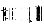
Страница 33: ...3 PHASE POWER CHASSIS MECHNICAL OUTLINE ...
Страница 34: ...BL3300 CONTROL CHASSIS MECHANICAL OUTLINE ...
Страница 35: ...BL33XX SERIES SINGLE PHASE POWER CHASSIS OUTLINE DRAWING 19 0 TYP 17 TYP 7 0 MAX ...
Страница 54: ...6 1 SECTION 6 PARTS LIST AND DRAWINGS f ...
Страница 56: ......
Страница 57: ......
Страница 58: ......
Страница 60: ......
Страница 62: ......


