


5
BL3300 SERIES MANUAL 01/28/2013
SECTION 2
UNPACKING AND INSTALLATION
2.1 UNPACKING
After unpacking the AC Source (unit), carefully conduct a thorough inspection of controls, indicators
and chassis. If the unit shows signs of damage, do not attempt to operate. File a damage claim with
the carrier responsible. Notify Behlman immediately.
2.2 INSTALLATION
!
WARNING
INSTALLATION AND OPERATION OF THIS EQUIPMENT EXPOSES VOLTAGE AND CURRENTS
THAT ARE HAZARDOUS. INSTALLATION MUST BE PERFORMED BY QUALIFIED PERSONNEL
ONLY.
1) This unit is intended to be mounted in an EIA standard 19 inch rack cabinet. This model consists of
two chassis. The input chassis houses the input transformer rectifiers and filters. The output of this
chassis is the DC operating voltages of +/-250VDC centered on the GND or common. The second
chassis ( control chassis ) houses the output inverters and all other active electronics. The system
is designed and tested with the control chassis in the top position. The keeps the maximum weight
at the bottom and provides the lowest center of gravity. T3 option unit have an additional outptu
chassis that should be mounted in the lowest position due to weight.
IMPORTANT
The chassis must have bottom support when mounting in a rack or a cabinet. Do not attempt to mount by
front panels only. These models pull cool air in through the side panels and exhaust heated air to the rear.
These units, when stacked, require proper cooling air circulation, one inch clearance between units and a
six inch clearance at the rear of the units. Rack enclosures must be ventilated.
2)
Ensure that the line circuit breaker and all other unit controls are in the OFF position before
connecting input power.
3)
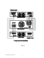
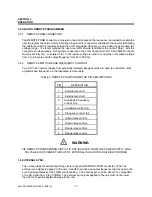
Connect 3 phase units as follows: ( refer to inter-connect diagrams provided on following pages.)
a)
INPUT POWER- Connect 47-63 Hz, power lines to the AC INPUT terminals designated:
N
A,
N
B,
N
C, and NEUTRAL . These are located on the rear of the input chassis and
designated as TB1. These connections require #10 ( 0.19") inside diameter ring lugs.
b)
OUTPUT POWER- Output power lines are connected to the
N
A,
N
B,
N
C, and NEUT
provided on the AC OUTPUT terminal strip on the rear of the control chassis. For T3
option units this terminal block is on the output chassis. These connections require 1/4"
inside diameter ring lugs. Use screws designated “WIRE THIS SIDE” only, removing the
other screws will cause mounting hardware to become loose and may fall into the unit.
c)
DC Interconnection between chassis:
Connect the HI, GND, and LOW DC output terminals of the power chassis to corresponding
DC input of the control chassis. Use the cables provided DO NOT USE LONGER WIRES.
Connect the two chassis together by connecting their chassis studs with cables provided. The
installation site protective earth ( safety ground ) should be connected to the rear panel
stud(s).
Содержание BL3300 Series
Страница 9: ...3 BL3300 SERIES MANUAL 01 28 2013 ALL MANUAL ADDENDUMS WILL FOLLOW THIS PAGE ...
Страница 15: ...9 BL3300 SERIES MANUAL 01 28 2013 SECTION 2 UNPACKING AND INSTALLATION ...
Страница 17: ...11 BL3300 SERIES MANUAL 01 28 2013 FIGURE 2 2 ...
Страница 20: ...14 BL3300 SERIES MANUAL 01 28 2013 ...
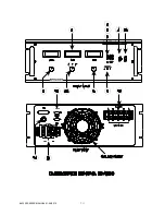
Страница 33: ...3 PHASE POWER CHASSIS MECHNICAL OUTLINE ...
Страница 34: ...BL3300 CONTROL CHASSIS MECHANICAL OUTLINE ...
Страница 35: ...BL33XX SERIES SINGLE PHASE POWER CHASSIS OUTLINE DRAWING 19 0 TYP 17 TYP 7 0 MAX ...
Страница 54: ...6 1 SECTION 6 PARTS LIST AND DRAWINGS f ...
Страница 56: ......
Страница 57: ......
Страница 58: ......
Страница 60: ......
Страница 62: ......


