ASSEMBLY INSTRUCTIONS
F-19858-6
Rev. 6-8-09 8-18-04
After you have all necessary components for this
installation, dig a trench below the frost line from
the water source to where the waterer will set.
Dig out about a 16" diameter hole beneath the
waterer for the 12" diameter Poly Earth Tube.
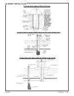
Refer to the diagrams on the next pages for water
pipe connection.
NOTE:
Install Shut-off Valve at
an easily accessible location.
If you have clay soil or a soil that does not drain
well, you will need to place about a foot of coarse
gravel for pipe drainage at the bottom of the hole.
Connect several Poly Earth Tubes together to
achieve your desired depth. Follow the installation
instructions on the label of the Poly Earth Tube.
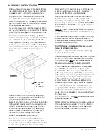
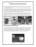
The Poly Earth Tube needs to be kept flush with
the top of your cement slab. Set the outside frame
of cement form and place a straight board or pipe
across the center of the hole. (see Figure 1
below).
Attach the Earth Tube to board by using long
screws or by plugging wire into the sides of the
tube and tying the tube to the board.
Back fill around the outside of the Poly Earth Tube
lightly at first, making sure the tube stays level at
the top. Continue to fill and tap lightly until hole
around the pipe is completely full. Avoid large
clods or rocks in this fill area. Pour the cement
level with the top of the Poly Earth Tube.
Waterer Installation Instructions
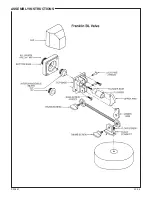
Remove valve cover and remove float valve
assembly. Disconnect the hose assembly from
the valve if the hose is attached. (In some models,
the hose is separate from the valve assembly.)
Remove the lid(s) and float balls from the waterer.
Locate the hardware package, it is generally
attached to the rim of the waterer body.
Attach the four Tie Down Brackets with the four
5/16" x 1½" lag screws. Use the small hole for
mounting to the waterer, the large hole will be used
for mounting to the concrete pad.
DO NOT OVER
TIGHTEN LAG SCREWS.
Just snug the bracket up
to the body.
NOTE:
These Tie Down Brackets are not required
on the SF-4C. The SF-4C has molded-in mounting
pads.
Turn the waterer upside down and place caulking
around the outer bottom edge. Make sure the
caulking is heavy enough to seal any irregularities
between drinker and cement.
CAUTION: Any air leakage in this area could
result in a frozen riser pipe.
Set in place with water line extended up through
tunnel. Anchor to concrete.
Slide insulating tube over water line and clamp with
plastic tie. Connect valve to water line and clamp
into position.
DO NOT OVER TIGHTEN BOLTS.
Make sure all waterline connections are tight.
Turn on water and adjust valve for desired water
level.
NOTE:
The waterer is equipped with a
Franklin Valve. This is an easy-to-maintain valve
with an operating range of 0 to 55 psi. It will work
with pond or low pressure gravity feed systems. If
increased flow is desired, a larger replacement
orifice (54300968) is available. If a gravity feed
system is used and more flow is desired, a low
pressure, high-flow valve (54130338) is available.
On units with ball closures, the 10" balls are pre-
weighted and foam filled to facilitate closing and
make it easier for smaller animals to access the
water. No further adjustment of ball weight should
be necessary.
Replace float cover.
DO NOT OVER TIGHTEN THE
TWO COVER BOLTS.
When animals are first exposed to a ball unit, lower
the water level approximately 1” to 2” so that the
ball floats freely. This allows the animals to learn
where the water is and how to drink from it.
Figure 1
Poly Earth
Tube
Extension
Содержание SF-2C
Страница 6: ...F 20441 4 7 06 ASSEMBLY INSTRUCTIONS ...


