background image

Chapter 6

56

Bedrock Secure OSA Remote User Manual   -  BRDOC020_001 

10/11/18

Monitoring and Troubleshooting

Overview

The Bedrock IDE System Monitor tool provides a graphical display that allows 
users to view and monitor the status of system components. The System Monitor 
tool is described in the Bedrock IDE online help.

In addition to the System Monitor tool, Bedrock Secure OSA Remotes provide 
LEDs on the front of the unit, a system logging feature, and status information 
in the Bedrock IDE to assist in troubleshooting. These troubleshooting methods 
are discussed in the following sections. It may also be necessary to look at code in 
the Bedrock IDE in order to troubleshoot control application issues.

Troubleshooting 
Flowchart

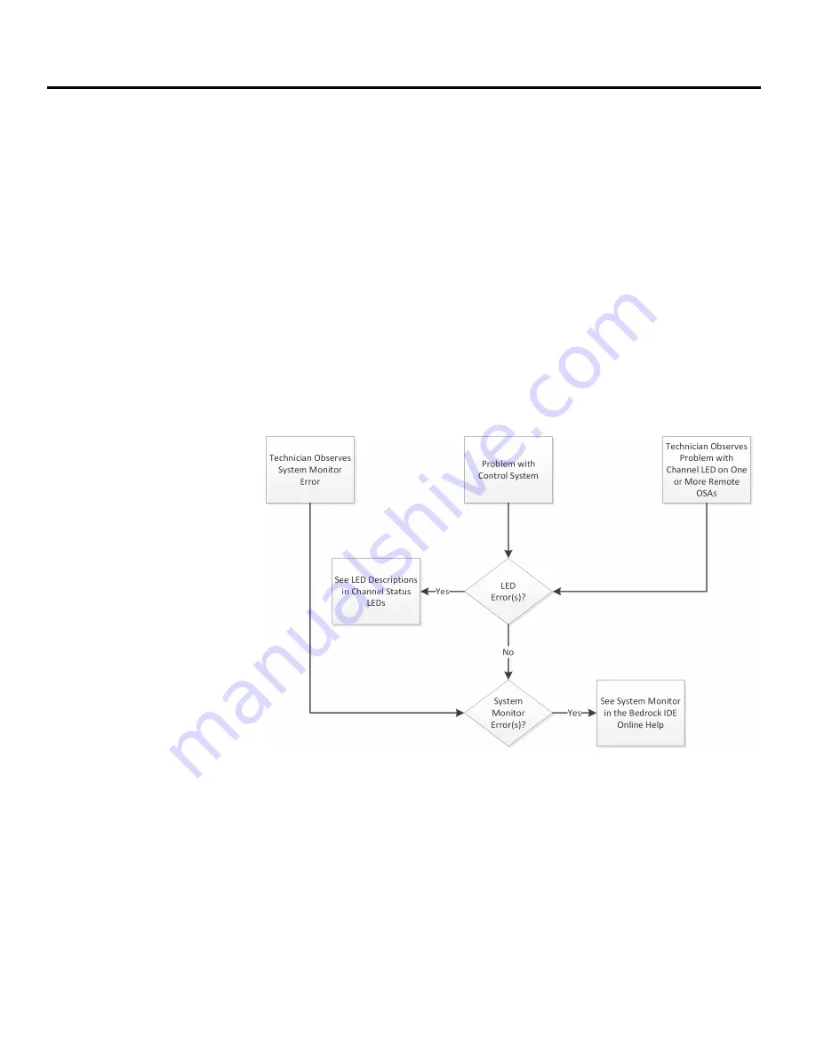
Follow the flowchart in Figure 6-1 should a user observe a problem with an OSA 
Remote.

Figure 6-1     

Troubleshooting Flowchart

General Troubleshooting 
Tasks

Use the LED blink codes to help determine which component may be 
compromised.

In addition to the channel status, LED blink codes, use the following list of 
troubleshooting techniques to help resolve system errors.

Verify that the OSA Remote has been correctly configured.

Содержание Secure OSA Remote

Страница 1: ...Bedrock Secure OSA Remote User Manual ...

Страница 2: ......

Страница 3: ... Connections 9 OSA Remote Operation 10 OSA Remote Power Input 10 OSA Remote Controller 10 Customer specific OPC UA Security Keys 11 Secure OPC UA Configuration 11 Secure Boot Software 12 MRAM and Data Persistence 12 IP Stack 12 Ethernet Communication 13 OPC UA 13 Analog and Discrete Input Output 13 Operating Modes 13 Simplified Circuit Diagram 14 Analog Data Format 14 Analog Accuracy Specification...

Страница 4: ... and CAN Bus Connections 27 Software Configuration 28 Analog and Discrete I O Parameters 28 Voltage Input Levels and Thresholds 30 Input Options and Sensor Types 30 Line Frequency Options 30 Analog to Digital Sampling Rates 30 I O Update Rate 31 Over Range Detection 31 Fail safe Output Feature 31 Digital Mode of Operation 32 Debounce Filter 32 Overcurrent Retry 33 Analog and Discrete I O Mapped Va...

Страница 5: ...4 Configuration 54 Observe 54 Diagnosis 54 Monitoring and Troubleshooting 56 Overview 56 Troubleshooting Flowchart 56 General Troubleshooting Tasks 56 Built in Self Test 57 OSA Remote LEDs 57 Status LED 58 Ethernet LEDs 58 Cyber LED 59 Channel LEDs 60 Storing Log Data in a Database 60 Default Configuration 61 ODBC Database Setup and Configuration 62 Logging Service Execution 64 Copying OSA Remote ...

Страница 6: ...cteristics 3 Field Wiring Requirements 3 Input Output Specifications 3 Power Specifications 7 HART Variables D 1 Log Messages E 1 Certifications and Standards F 1 Certifications 1 Underwriters Laboratories UL Safety Compliance 1 CE Testing 1 IEC Environmental Testing 1 EIA Publication 364 2 FCC Testing 3 Standards 3 IEC 61131 3 Acronyms G 1 ...

Страница 7: ...t that The information in this manual is complete true accurate or non misleading The Bedrock Secure OSA Remote User Manual is provided solely for informational purposes You should not act upon information without consulting Bedrock Automation Subject to Change The Bedrock Secure OSA Remote User Manual is subject to change without notice Exceptions Nothing in this disclaimer will exclude or limit ...

Страница 8: ......

Страница 9: ...e inputs and outputs or NAMUR sensors The available operating modes are listed in the next section Additional detail is provided in Analog and Discrete Input Output OSA Remote Offerings Both ten and twenty channel OSA Remote models are available with a standard 8 GB of flash memory or an optional 32 GB of flash memory Table 1 1 lists the available OSA Remote models Customer specific OPC UA securit...

Страница 10: ...red discrete output with readback maximum current of 1 amp NAMUR 0 10 V voltage input discrete input Power to the OSA Remote is provided by a 9 30 V DC input Two Ethernet ports for connection to a Bedrock Control System workstation via a local intranet and to third party devices A serial port that provides RS 232 RS 485 or RS 422 communication to third party devices A CAN bus port provides an inte...

Страница 11: ...8 Bedrock Secure OSA Remote User Manual BRDOC020_001 3 A dimensional diagram of an OSA Remote is shown in Figure 1 1 Each side of the OSA Remote has two of the four twenty pin I O connectors Figure 1 1 OSA Remote with Dimensions 137 mm 226 mm 46 mm 59 mm ...

Страница 12: ...emote Bottom View Bedrock Secure OSA Remote Architecture The advanced design features of the OSA Remote architecture provide Maximized throughput of sensor data Accurate timekeeping and coordination with super capacitor backed real time clock High speed control loops A more secure and robust system through the choice of Point to point I O communication Real Time Operating System RTOS Active encryp...

Страница 13: ...iew Chapter 1 10 11 18 Bedrock Secure OSA Remote User Manual BRDOC020_001 5 A block diagram of the Bedrock Secure OSA Remote CPU board is shown in Figure 1 3 Figure 1 4 shows the I O subsystem Figure 1 3 OSA Remote CPU Board Diagram ...

Страница 14: ...I O Subsystem Security The OSA Remote is designed with the security features listed below Secure boot including an encrypted and signed image Transport Layer Security TLS with X 509 certificates used on all workstation communication channels Certificates and cryptographic keys with a usable lifetime projected beyond the year 2030 ...

Страница 15: ...mote the Bedrock Integrated Development Environment IDE the Bedrock Field Device Tool FDT for configuring the OSA Remote to communicate with field devices that support the HART Communication Protocol See the HART Device Configuration chapter for more information Connectivity The following are the requirements for OSA Remote communication connections OSA Remote Ethernet Connections Communication ov...

Страница 16: ... cable is available in increments of one meter up to a maximum length of 30 meters See Appendix A Part Numbers for information on ordering the Bedrock Universal Cable Bedrock UTAs Bedrock Universal Termination Assemblies UTAs are DIN rail mounted screw terminals that simplify connections between OSA Remotes and field devices The Bedrock Dual head Universal Cable is used to make the connection betw...

Страница 17: ...n CAN I O Port Connections A CAN I O port is also provided to support CAN bus communication between the OSA Remote and devices using the CAN bus protocol The Bedrock Universal Serial Communication Cable is available as an option for connecting the OSA Remote to other devices via the CAN I O port See CAN Bus Port Wiring in Wiring Diagrams and Pin Out Information for wiring information for the CAN b...

Страница 18: ...power supply for the 9 30 V DC input See OSA Remote Power Input in Hardware Installation for information on power connections including cabling and pin outs OSA Remote Controller Bedrock Secure OSA Remotes feature a microcontroller that provides the operating system network communications provisions for hardware configuration and management of system operations The OSA Remote microcontroller scans...

Страница 19: ...te that is being upgraded A separate client certificate is required for any OPC UA client software to be able to connect to a OSA Remote that is configured with customer specific security certificates OPC UA client certificates are specific to each OPC UA client application Contact Bedrock Automation for guidance on upgrading OSA Remotes and configuring software with customer specific security cer...

Страница 20: ...et Origin function in the Bedrock IDE Retain variables are restored after a warm reset They are cleared using the Reset Origin function in the Bedrock IDE Refer to the Bedrock IDE online help for information on how to implement persistent and retained variables in your application Note that an application program in the Bedrock IDE must have its task interval set to 5 ms or greater to ensure that ...

Страница 21: ...isit the OPC foundation website at https opcfoundation org Analog and Discrete Input Output Each universal I O channel on an OSA Remote can be independently configured to operate in one of several modes Depending upon the mode selected OSA Remote channels can interface to analog inputs and outputs with or without HART discrete inputs and outputs or NAMUR sensors Operating Modes The operating modes...

Страница 22: ...tputs the readback value shown in the Bedrock IDE will not change unless there is a connected load Discrete outputs can be used to readback current up to 1 amp Simplified Circuit Diagram Figure 2 2 shows a simplified circuit diagram of an OSA Remote I O channel Figure 2 2 OSA Remote Simplified Circuit Diagram Analog Data Format The analog data is 32 bit floating point IEEE 754 format ...

Страница 23: ...ured for discrete output a channel can utilize an electronic fuse that will disable the channel if the current exceeds a programmable threshold up to 1 amp Each channel s electronic fuse can be configured to latch off or auto retry during an overcurrent condition When the channel has been latched off the channel must be disabled turned off to clear the fault condition Channel faults can be detecte...

Страница 24: ...cure OSA Remote User Manual BRDOC020_001 10 11 18 Figure 2 3 Externally Sourced Discrete Output Figure 2 4 Internally Sourced Discrete Output Discrete Output Accuracy The discrete output current measurement is accurate to within 1 5 of full scale ...

Страница 25: ...ete input channel is configurable for discrete on off detection or the channel can be used for frequency measurement from 10 Hz to 100 kHz Each channel can also be used for pulse accumulation Up to 4 billion pulses can be captured Pulses are captured on falling edges NAMUR An OSA Remote can be configured to interface to a NAMUR output sensor The NAMUR sensor will provide a low level current to the...

Страница 26: ...tion Wiring the Module See Appendix B Wiring Diagrams and Pin Out Information for OSA Remote wiring information Module Fault and Status Indication See OSA Remote LEDs in Monitoring and Troubleshooting for the list of blink codes used to indicate status for OSA Remotes Serial I O The OSA Remote serial channel has its own processor as shown in Figure 2 6 The Programmable Level Controller processes t...

Страница 27: ...OSA Remote Operation Chapter 2 10 11 18 Bedrock Secure OSA Remote User Manual BRDOC020_001 19 Figure 2 7 Programmable Level Controller ...

Страница 28: ...ained in the installation instructions Hazardous Location Information WARNING EXPLOSION HAZARD DO NOT CONNECT OR DISCONNECT AN OSA REMOTE WHILE IT IS ENERGIZED Important Note the following with regard to installation of the Bedrock OSA Remote in hazardous locations THE EQUIPMENT IS AN OPEN TYPE DEVICE MEANT TO BE INSTALLED IN AN ENCLOSURE SUITABLE FOR THE ENVIRONMENT AND THAT IS ONLY ACCESSIBLE WI...

Страница 29: ...ements in the application of the system and shall be trained in use of the system Optical Ports Attention Under certain conditions viewing the optical port may expose the eye to hazard When viewed under some conditions the optical port may expose the eye beyond the maximum permissible exposure recommendations Bedrock OSA Remotes are Class 1 laser products pursuant to FDA CDRH and EN IEC 60825 regu...

Страница 30: ...OSA Remote The Bedrock Secure OSA Remote can be mounted onto a sheet metal panel or cabinet by inserting four 10 sheet metal screws through four right angle brackets that can be attached to the top and bottom of the OSA Remote enclosure See Figure 3 1 Figure 3 1 OSA Remote Panel Mount Alternatively the Bedrock Secure OSA Remote can be mounted onto a DIN rail by inserting two 10 sheet metal screws ...

Страница 31: ...es a 9 30 V DC power source It is recommended that SPM DC Input Power Cable from Bedrock Automation be used for providing DC power to the OSA Remote Alternatively a user provided cable may be used The SPM DC Input Power Cable and pin out information is shown in Figure 3 3 Connect the drain wire to earth ground Figure 3 3 SPM DC Input Power Cable PIN 3 PIN 2 PIN 1 PIN NO COLOR FUNCTON PIN 3 GREEN G...

Страница 32: ... on each connector allow the connectors to be securely fastened to the module Figure 3 4 OSA Remote Bottom View Labels and functions of the three pin power connectors are listed in Table 3 1 Table 3 2 lists the power input requirements DC Power In Serial Connection CAN bus Connection Ethernet Ports Table 3 1 System Power Connector Pin Out Label Function Safety ground for system Power return Power ...

Страница 33: ...pper or fiber optic cable from one of the RJ45 connectors labeled A and B in Figure 3 4 to a networked device such as a Bedrock Control System workstation The following are the Cat6 shielded copper cable specifications 10 100 1000 Mbps full and half duplex communication 100 m maximum cable length The following are the fiber optic cable specifications 9 125 μm single mode fiber SMF 1310 nm waveleng...

Страница 34: ...s located on the cable assembly secure the assembly to the OSA Remote twenty pin I O connectors Connect the assembly to the OSA Remote as shown in Figure 3 5 Figure 3 5 Bedrock Universal Cable Connected to OSA Remote The wiring diagram and pin outs for the universal cable and OSA Remote connectors are shown in Figure 3 6 Connect the drain wire to earth ground ...

Страница 35: ...er end of the cable has a 9 pin female D Sub connector the same as can be found on a standard PC for connection to field devices See Appendix B Wiring Diagrams and Pin Out Information for pin out information for the supported serial communication standards PIN 1 PIN 2 PIN 3 PIN 4 PIN 5 PIN 6 PIN 7 PIN 8 PIN 9 PIN 10 PIN 11 PIN 12 PIN 13 PIN 14 PIN 15 PIN 16 PIN 17 PIN 18 PIN 19 PIN 20 WIRING DIAGR...

Страница 36: ...OSA Remote Parameters in the Bedrock IDE Table 4 1 OSA Remote Configurable Parameters Parameter Name Description Point Name User assigned name for the I O point Mode for Channel Operating mode for the channel See Operating Modes in OSA Remote Operation for a list of the OSA Remote operating modes Input Voltage Level Input voltage level for the module The on and off thresholds are shown in Table 4 ...

Страница 37: ... debounce filtering For modes supporting discrete input or NAMUR Digital Out Retry Period Number of milliseconds 3 255 between retries in an overcurrent situation This parameter is ignored if Digital Out Retry Limit is zero For mode supporting discrete output Digital Out Retry Limit Number of retries up to 255 in an overcurrent situation If set to zero the channel stays latched off For mode suppor...

Страница 38: ...e frequency options are configurable to accommodate different locales The supported line frequency options for the OSA Remote are 50 Hz 60 Hz Analog to Digital Sampling Rates The analog to digital converter sampling rates and resolutions available for the OSA Remote in the Bedrock IDE are shown in Table 4 4 The sampling rates available are dependent on the line frequency and are measured in sample...

Страница 39: ...s received from the CPU within the configured fail safe timeout period and the fail safe mode configuration parameter is set to Fail safe the output for each channel will be set to either a configured fail safe value or held at the current level Table 4 4 A D Sampling Rates and Resolutions Sampling Rate SPS at 50 Hz Line Frequency Sampling Rate SPS at 60 Hz Line Frequency Resolution in Bits 8 10 1...

Страница 40: ...ecommended modes for the listed input frequencies Note that regardless of the mode selected the digital counter and frequency values will all update in the Bedrock IDE The most accurate value will be the one corresponding to the selected mode Debounce Filter The OSA Remote has a programmable debounce filter The debounce filter can be set to values of 0 255 milliseconds If the filter is set to zero...

Страница 41: ...off and retry Use the Bedrock IDE to specify the overcurrent threshold maximum current allowed before a fault occurs number of retries and time period between retries A channel will stay latched off if the retry limit is set to zero Additional detail pertaining to OSA Remote configuration parameters appears below Analog and Discrete I O Mapped Variables OSA Remote variables available for mapping t...

Страница 42: ...field is used Table 4 7 lists the mapped variable name variable type and applicable operating mode for which the variable is used Table 4 7 OSA Remote Mapped Variables Variable Type Applies to Operating Mode s with the Listed Functionality Requested Analog REAL analog output Input Analog REAL analog output analog input digital output NAMUR Input Analog Status WORD analog output analog input digita...

Страница 43: ...og REAL analog output Requested Digital Values WORD digital output Input Digital Values WORD digital input digital output NAMUR Output Digital Values WORD digital output Input Voltage REAL Measured voltage input into the OSA Remote Not specific to an individual channel or operating mode IO Temperature REAL Measured temperature of the OSA Remote I O subsystem Not specific to an individual channel o...

Страница 44: ...30 400 bps Parity Specifies parity for the serial port NO_PARITY EVEN even number of one bits ODD odd number of one bits Data Bits Number of data bits per character 5 6 7 or 8 Stop Bits Number of stop bits per character 1_STOP_BIT one stop bit will be used 1 5_TO_2_STOP_BITS 1 5 stop bits when using 5 data bits otherwise 2 stop bits Rx Enable Set to TRUE to enable receive function for the serial p...

Страница 45: ...Parameters that are configurable in the Bedrock IDE for the OSA Remote CAN bus port are shown in Figure 4 6 and summarized in Table 4 10 Figure 4 6 CAN Bus Parameters Tx LED Enable Set to TRUE to enable transmit LED for the serial port Loopback Enable Set to TRUE to use the Rx line to verify that data was transmitted correctly Disables the external receiver Terminator Enable Enables 120 ohm termin...

Страница 46: ...on using the Bedrock Field Device Tool to configure an OSA Remote for communication with field devices that support the HART Communication Protocol see HART Device Configuration For a list of HART variables available in the Bedrock IDE see Appendix D HART Variables Table 4 10 CAN Bus Parameters Parameter Name Description Baud Rate The baud rate for the CAN bus I O port can be set to one of the fol...

Страница 47: ... a digital communication link between host systems and smart field devices HART passthrough is supported using the Bedrock FDT For a list of available HART variables see Appendix D HART Variables The Bedrock IDE provides the ability to map HART variables to your control program For more information on the HART Communication Protocol see the HART Communication Foundation website http www hartcomm o...

Страница 48: ...ol is installed during installation of the Bedrock IDE A shortcut to the FDT is created on the workstation s desktop Bedrock DTMs are also installed during installation of the Bedrock IDE Bedrock DTMs will be available when configuring HART devices described below DTMs for third party field devices are installed separately Contact the device manufacturer to obtain any files needed for installation...

Страница 49: ...Windows Security prompt may be displayed Select the displayed certificate or choose another certificate to use for connecting to the remote When attempting an initial connection to an OSA Remote the OSA Remote will respond with a certificate An Authorize Certificate prompt will be displayed in the Bedrock FDT Authorization of the certificate is required to continue configuration The Windows Securi...

Страница 50: ...installed Installation of the Bedrock IDE includes the Bedrock FDT and Bedrock DTMs Ensure that the software is up to date 2 Ensure that any DTMs from third party device manufacturers have been installed 3 Create a blank project from the start page of the Bedrock FDT A network node will be highlighted in the Network View see Figure 5 3 If the DTMs were installed for the first time or if existing D...

Страница 51: ... 43 Figure 5 3 New FDT Project 4 Select a Bedrock communication DTM from the Device Catalogue as shown in Figure 5 4 A secure version of a DTM should be selected Figure 5 4 Select Communication DTM 5 Double click the communication DTM that was just added to the Network View as shown in Figure 5 5 ...

Страница 52: ...te User Manual BRDOC020_001 10 11 18 Figure 5 5 Select Network Adapter 6 In the Network Card Selection pane select the network card for the OSA Remote that you are trying to connect to from the drop down menu as shown in Figure 5 6 Figure 5 6 Select Network Device ...

Страница 53: ...r Local Interconnect DTM The DTM can be added either automatically or manually Select the communication DTM in Network View and then choose one of the following To automatically add a Controller Local Interconnect DTM click Scan and Select on the Topology tab in the Ribbon The Bedrock FDT will query the network for available OSA Remotes Go to step 9 Or to manually add a DTM to your network topolog...

Страница 54: ... add to your project and then do one of the following Click Add All and Close This will add all compatible DTMs in the list to your project Or click Add Selected Nodes to Project This will add only those DTMs with check marks to your project Click Close to dismiss the dialog Figure 5 8 Adding Gateway DTMs After Scan 10 The Network View pane will be updated with the selected DTM s as shown in Figur...

Страница 55: ...SA Remotes Go to step 12 Or to manually add a gateway DTM for SIO Hart to your network topology without querying the network click the plus sign next to the DTM in the Device Catalogue that is named Bedrock SIO Hart 6 20 ANALOG Go to step 13 12 If you elected to automatically add a DTM Scan and Select in the previous step a list of the DTMs that were found will be displayed as shown in Figure 5 10...

Страница 56: ...001 10 11 18 Figure 5 10 Adding DTM After Scan 13 Once gateway DTMs for SIO Hart have been added to your project the Network View pane will be updated as shown in Figure 5 11 Select the Bedrock SIO Hart 6 20 ANALOG DTM to see a list of device DTMs for HART devices in the Device Catalogue ...

Страница 57: ... following To automatically add a device DTM for a HART device click Scan and Select on the Ribbon as shown in Figure 5 11 Or to manually add a device DTM to your network topology without querying the network click the plus sign next to the DTM name in the Device Catalogue 15 You will be prompted for a list of channels to scan as shown in Figure 5 12 These correspond to channels on the OSA Remote ...

Страница 58: ...e DTM A list of the DTMs that were found will be displayed as shown in Figure 5 13 Use the checkbox to select the DTM s you would like to add to your project and then do ones of the following Click Add All and Close This will add all compatible DTMs in the list to your project Or click Add Selected Nodes to Project This will add only those DTMs with check marks to your project Click Close to dismi...

Страница 59: ...ll be updated with device DTMs as shown in Figure 5 14 Do one of the following If you elected to automatically add a DTM in step 14 then select a device DTM and click the Connect button on the Device tab on the Ribbon to connect to a HART device Or if you elected to manually add a DTM in step 14 then go to step 19 Figure 5 14 Device DTM Added to Network View ...

Страница 60: ...section summarizes common functions that are available in the Bedrock FDT user interface In addition to being located on the FDT Ribbon these functions can also be accessed from context menus right clicking Topology Tab The following functionality is available on the Topology Tab located on the Bedrock FDT Ribbon Import from XML Reads previously saved topology information from an XML file Export t...

Страница 61: ...t from selected device This option is available for all DTMs Load from Device This option is available for HART Devices Parameters from the device are loaded into the FDT memory If the device state is Disconnected the FDT will attempt to connect to the device Store to Device This option is available for HART Devices Parameters in the FDT memory are stored to the selected device If the device state...

Страница 62: ...e device must be in the Connected state for this option to be selected Behavior is specific to the selected device DTM Configuration Allows configuration of a device such as selection of a network card for a Communication DTM Observe Allows observation of device operation Behavior is specific to the selected device DTM Diagnosis Displays diagnostic information for the selected device Behavior is s...

Страница 63: ...HART Device Configuration Chapter 5 10 11 18 Bedrock Secure OSA Remote User Manual BRDOC020_001 55 Figure 5 17 Diagnostic Information for a HART Device ...

Страница 64: ...the Bedrock IDE to assist in troubleshooting These troubleshooting methods are discussed in the following sections It may also be necessary to look at code in the Bedrock IDE in order to troubleshoot control application issues Troubleshooting Flowchart Follow the flowchart in Figure 6 1 should a user observe a problem with an OSA Remote Figure 6 1 Troubleshooting Flowchart General Troubleshooting ...

Страница 65: ...nel The OSA Remote LEDs will be turned on and off This allows the user to visually verify that the OSA Remote LEDs are functioning OSA Remote LEDs LEDs located on the front of Bedrock Secure OSA Remotes provide information about the operational status of the unit The LEDs are shown in Figure 6 2 Figure 6 2 OSA Remote LEDs The LEDs indicate the status of OSA Remote operation as follows The Status L...

Страница 66: ...ed LEDs indicate normal operation while flashing LEDs indicate an error condition See Channel LEDs and Table 6 5 Status LED The Status LED provides system status including information about the boot process and authentication Table 6 1 shows the states of the System Status LED Ethernet LEDs OSA Remotes have Ethernet Status LEDs for each Ethernet port These LEDs indicate the status of the Ethernet ...

Страница 67: ...twork 2 Yellow Solid Boot completed Ethernet link good 3 Yellow Flashing Indicates Ethernet traffic Table 6 3 Cyber LED States During Startup Item No LED Color LED Status Description 1 None OFF Cyber LED is off during startup 2 Red Solid Operating system is running 3 Purple Solid OSA Remote is ready to load security keys and certificates 4 Purple Fast Flash No keys or certificates available to loa...

Страница 68: ...ion errors and warnings The BedrockLogMonitor service uses an ODBC driver to write log entries to the database 4 Blue Flashing There was an unexpected attempt to connect to the OSA Remote 5 Green Solid Keys and certificates have been loaded and validated Table 6 4 Cyber LED Behavior During System Operation Item No LED Color LED Status Description Table 6 5 OSA Remote Channel LEDs Item No LED Color...

Страница 69: ...flash memory to the workstation by using the file transfer capability of the built in to the Bedrock IDE See Copying OSA Remote Log Files Default Configuration By default OSA Remote log data is written to a local SQLite database The default location for the SQLite database is IDE_install_dir Log Monitor Log db3 where IDE_install_dir is the installation location of the Bedrock IDE By default that l...

Страница 70: ...hen OSA Remotes are selected or deselected in the Bedrock IDE see below Database connection information ODBCConnectionString and LogTableName must be entered by manually editing the configuration file Table 6 6 Logging Service Parameters Parameter Description ODBCConnectionString Database connection information for the ODBC driver Required for BedrockLogMonitor This information must be modified ma...

Страница 71: ... ensure that the 64 bit version of the tool is used to create a System DSN Figure 6 4 If connecting to a local database enter the database filename e g Log db3 in the ODBConnectionString element Figure 6 3 Sample XML Configuration File LocalCertificateThumbprint The thumb print of the certificate to use from the local machine key store that identifies the workstation to the OSA Remote RemoteCertif...

Страница 72: ...manually can be done using standard Windows procedures e g Windows Control Panel entering services msc in the Windows Run dialog using the net command from the Windows command prompt etc Logging Service Execution Once BedrockLogMonitor is started and configuration parameters are sent to the OSA Remote it will periodically send requests for log records via an Ethernet socket to the OSA Remotes that...

Страница 73: ...ure OSA Remote User Manual BRDOC020_001 65 OSA Remote s The status of the BedrockLogMonitor service is available in the Windows Event Viewer Application Log Figure 6 5 provides an overview of system logging in the Bedrock Control System Figure 6 5 System Logging ...

Страница 74: ...hown in the following format YYYY MM DD HH MM SS fff msgtype Message Type String indicating the type of log message STARTUP SHUTDOWN CONFIG UPDATE RUNTIME WARNING ERROR sio Module Type String that identifies the message source controller IO or power chnum Channel Number Communication channel used by the module 1 5 devtag Device Tag Manufacturer supplied string containing module information errcode...

Страница 75: ... that this sequence assumes that the user is logged into the OSA Remote 1 Double click an OSA Remote in the Devices pane of the Bedrock IDE Figure 6 6 This will display the device editor Figure 6 7 Figure 6 6 Devices Pane Figure 6 7 Devices Pane and Device Editor 2 Select the files tab in the device editor Figure 6 8 Two lists will be displayed The list on the left will show the file system for th...

Страница 76: ...uble click the log folder in the right pane A list of log files will be displayed Figure 6 9 Figure 6 9 Log Files 4 In the left pane Figure 6 8 navigate to the local destination for the log files In the right pane select the log files to copy 5 Use the arrow buttons between the lists to copy the selected files to the destination folder ...

Страница 77: ...en Status Information Status and diagnostic information for an OSA Remote can be viewed by using the Device Management feature in the Bedrock IDE Access status information as follows 1 In the Bedrock IDE select Device Management from the Tools menu as shown in Figure 6 10 Figure 6 10 Select Device Management 2 In the Device Management window Figure 6 11 select an OSA Remote from the list of device...

Страница 78: ...nd diagnostic information to be displayed as follows The System Status tab displays diagnostic information for OSA Remote components and subsystems The I O Status tab displays information for each OSA Remote I O channel The Log tab displays OSA Remote log entries Selecting the Log to File checkbox will cause log entries to be written to a local text file while the OSA Remote Status window is open ...

Страница 79: ...20 R20 8X Firmware upgrade at the factory or in the field for OSA Remote R20 8 models Enables user custom cyber root keys Required to support secure OPC UA and SCADA security BROSAX20 R20 32 Secure Universal 20 Channel Remote Controller 32 GB Flash BROSAR2H R20 32X Firmware upgrade at the factory or in the field for OSA Remote R20 32 models Enables user custom cyber root keys Required to support s...

Страница 80: ...ication Cable BRCBLSER SFP F Fiber Ethernet SFP Interface Module OP00003 SFP C Copper Ethernet SFP Interface Module OP00008 Bedrock OSA Remote Mounting Stand BROSARMS UTA CP Universal Termination Assembly with PWR Dist BRUTA00P UTA CN Universal Termination Assembly with No PWR Dist BRUTA00N Table A 2 Assembly Part Numbers Model Number Description Part Number ...

Страница 81: ...onnectors with channel numbers is shown in Figure B 1 Figure B 1 OSA Remote Connector Locations I O Connector Pin Outs OSA Remote pin out information is shown in the following tables Channel 1 Channel 2 Channel 4 Channel 3 Channel 5 Channel 10 Channel 6 Channel 9 Channel 8 Channel 7 Channel 20 Channel 11 Channel 17 Channel 15 Channel 18 Channel 12 Channel 13 Channel 19 Channel 14 Channel 16 Table ...

Страница 82: ...AIR 10 19 CHAN 5 RETURN 20 CHAN 5 DISCRETE Table B 2 OSA Remote Pin Outs for Channels 6 10 Pair No Pin No Function PAIR 1 1 CHAN 6 EXCITATION 2 CHAN 6 ANALOG PAIR 2 3 CHAN 6 RETURN 4 CHAN 6 DISCRETE PAIR 3 5 CHAN 7 EXCITATION 6 CHAN 7 ANALOG PAIR 4 7 CHAN 7 RETURN 8 CHAN 7 DISCRETE PAIR 5 9 CHAN 8 EXCITATION 10 CHAN 8 ANALOG PAIR 6 11 CHAN 8 RETURN 12 CHAN 8 DISCRETE PAIR 7 13 CHAN 9 EXCITATION 14...

Страница 83: ...IR 6 11 CHAN 13 RETURN 12 CHAN 13 DISCRETE PAIR 7 13 CHAN 14 EXCITATION 14 CHAN 14 ANALOG PAIR 8 15 CHAN 14 RETURN 16 CHAN 14 DISCRETE PAIR 9 17 CHAN 15 EXCITATION 18 CHAN 15 ANALOG PAIR 10 19 CHAN 15 RETURN 20 CHAN 15 DISCRETE Table B 4 OSA Remote Pin Outs for Channels 16 20 Pair No Pin No Function PAIR 1 1 CHAN 16 EXCITATION 2 CHAN 16 ANALOG PAIR 2 3 CHAN 16 RETURN 4 CHAN 16 DISCRETE PAIR 3 5 CH...

Страница 84: ... Secure OSA Remote User Manual BRDOC020_001 10 11 18 PAIR 8 15 CHAN 19 RETURN 16 CHAN 19 DISCRETE PAIR 9 17 CHAN 20 EXCITATION 18 CHAN 20 ANALOG PAIR 10 19 CHAN 20 RETURN 20 CHAN 20 DISCRETE Table B 4 OSA Remote Pin Outs for Channels 16 20 Pair No Pin No Function ...

Страница 85: ... diagrams for connecting the OSA Remote to field devices Figure B 2 OSA Remote 4 20 mA Internal Loop Powered Transmitter Figure B 3 OSA Remote 4 20 mA External Loop Powered Transmitter Ch 5 10 15 20 Ch 4 9 14 19 Ch 3 8 13 18 Ch 2 7 12 17 Ch 1 6 11 16 LOOP POWERED TRANSMITTER T Ch 5 10 15 20 Ch 4 9 14 19 Ch 3 8 13 18 Ch 2 7 12 17 Ch 1 6 11 16 LOOP POWERED TRANSMITTER POWER SUPPLY T ...

Страница 86: ...e User Manual BRDOC020_001 10 11 18 Figure B 4 OSA Remote 4 20 mA Output with Internal Readback Figure B 5 OSA Remote Discrete Input Contact Closure Ch 5 10 15 20 Ch 4 9 14 19 Ch 3 8 13 18 Ch 2 7 12 17 Ch 1 6 11 16 Ch 5 10 15 20 Ch 4 9 14 19 Ch 3 8 13 18 Ch 2 7 12 17 Ch 1 6 11 16 ...

Страница 87: ...mote User Manual BRDOC020_001 B 7 Figure B 6 OSA Remote Discrete Input Voltage Monitor Figure B 7 OSA Remote Discrete Output Internal Excitation Ch 5 10 15 20 Ch 4 9 14 19 Ch 3 8 13 18 Ch 2 7 12 17 Ch 1 6 11 16 V Ch 5 10 15 20 Ch 4 9 14 19 Ch 3 8 13 18 Ch 2 7 12 17 Ch 1 6 11 16 LOAD ...

Страница 88: ... Manual BRDOC020_001 10 11 18 Figure B 8 OSA Remote Discrete Output External Excitation Figure B 9 OSA Remote NAMUR Sensor Ch 5 10 15 20 Ch 4 9 14 19 Ch 3 8 13 18 Ch 2 7 12 17 Ch 1 6 11 16 LOAD POWER SUPPLY Ch 5 10 15 20 Ch 4 9 14 19 Ch 3 8 13 18 Ch 2 7 12 17 Ch 1 6 11 16 T NAMUR SENSOR ...

Страница 89: ...n Out Information Appendix B 10 11 18 Bedrock Secure OSA Remote User Manual BRDOC020_001 B 9 Figure B 10 OSA Remote 0 10 Volt Input Ch 5 10 15 20 Ch 4 9 14 19 Ch 3 8 13 18 Ch 2 7 12 17 Ch 1 6 11 16 V EXTERNAL VOLTAGE SOURCE ...

Страница 90: ... PC for connecting to serial devices The pin out for each connector is the same The Micro D connector with pin numbers is shown in Figure B 11 Important Note that a shielded cable tied to the OSA Remote enclosure is required to comply with product safety certifications Figure B 11 Serial Cable Pin Numbering The pin out information for each serial operating mode is shown in Table B 5 Note that each...

Страница 91: ... 9 pin female D Sub connector connects to CAN bus field devices The pin out for each connector is the same The Micro D connector is shown in Figure B 11 Important Note that a shielded cable tied to the OSA Remote enclosure is required to comply with product safety certifications The pin out information for the CAN bus port is shown in Table B 6 Table B 6 CAN Bus Communication Pin Out Information P...

Страница 92: ...C 1 OSA Remote General Specifications Specification Value Processor Dual Core ARM Cortex processor RAM 512 MB ECC RAM Flash Memory 8 GB standard 32 GB optional MRAM 8 kB Control Cycle Time 3 ms RTOS Green Hills INTEGRITY Open Control Package Support Bedrock IDE Ethernet Communication 1 Gbit Dual SFP Fiber or Copper transceiver slots IP Stack Dual mode IPv4 IPv6 Power Requirement 9 30 V 25 W max po...

Страница 93: ...UR 0 10 V voltage input discrete input Channels may also be configured as a spare Serial Communication Standards RS 232 RS 422 RS 485 Serial Connections 1 CAN Bus Connections 1 Power Consumption 24 watts Power Dissipation 15 watts The channels are galvanically isolated from each other and galvanically isolated from ground Channel to channel 500 V Channel to ground 500 V Operating Temperature 40 C ...

Страница 94: ...n accessory for connecting the OSA Remote to field devices It is available in standard lengths of 1 3 or 5 meters It can also be ordered in custom lengths See Table A 2 for model and part number information Input Output Specifications Each OSA Remote I O channel can be independently configured for one of the operating modes described in Table C 1 Depending upon the mode selected the following func...

Страница 95: ...utputs internally sourced discrete outputs Table C 3 OSA Remote Analog Specifications Specification Value Loop Compliance Voltage 18 V DC minimum at 22 mA Current Inputs Sense Resistor 250 Ω software selectable Analog Output Load Resistance Minimum 250 Ω Analog Output Load Resistance Maximum 750 Ω 4 20 mA Analog Input Current Accuracy 0 03 of full scale at 23 C Analog Input Voltage Accuracy 0 035 ...

Страница 96: ...Accuracy 0 035 of full scale Table C 5 Specifications for Contact Sense Inputs Specification Value Maximum Voltage on Excitation 25 V Filter Debounce Time Programmable 0 255 ms Frequency Accuracy 0 035 of full scale Table C 6 Specifications for Externally Sourced Discrete Outputs Specification Value Maximum On Current 1 amp Maximum Switching Voltage 30 V Programmable Overcurrent Shutoff Latch off ...

Страница 97: ... Voltage 30 V DC Overcurrent Limit Soft selectable up to 1 0 amps Discrete Output Current Accuracy 1 5 of full scale Table C 7 Specifications for Internally Sourced Discrete Outputs Specification Value Maximum Voltage on Excitation 25 V Maximum Current 25 mA Discrete Output Current Accuracy 1 5 of full scale Table C 8 NAMUR Specifications Specification Value NAMUR Impedance 1 kΩ NAMUR Sensor Failu...

Страница 98: ...30 V DC power input Table C 9 lists the electrical specifications for the OSA Remote power input Table C 9 Power Input Specifications Specification Value Input Voltage Range DC 9 30 V DC the OSA Remote turns on at 10 V and off below 9 V Input Fuse DC 4 A Input Protection Transient Surge Protection Clamp Voltage 33 V Voltage Monitor Input Accuracy 1 ...

Страница 99: ...ART device state for each channel See Table D 5 for the HART device states The HART Device Data Parameters tab in the Bedrock IDE provides a HART Device Address parameter for each channel Entering a value of 0 15 specifies an address of a HART device A value of 16 is used for auto scan Setting a channel for auto scan will cause the OSA Remote to scan from address 0 15 The first HART device found w...

Страница 100: ... Span 4 bytes Float Private Label Distributor Code 1 byte Integer Number Sensor Unit Code 1 byte 1 255 Number of Preambles 1 byte Integer Number Range Units 1 byte 1 255 Poll Address 1 byte Integer Number Manufacturer ID 1 byte 1 255 Device Type 1 byte Integer Number Universal Command Revision 1 byte Integer Number Device specific Command Revision 1 byte Integer Number Software Revision 1 byte Int...

Страница 101: ...alue Out of Limit Other value outside of high or low limit Loop Current Saturated Loop current past high limit Loop Current Fixed Loop current forced to a fixed value More Status Available Extra status bits are available Cold Start Device has restarted Configuration Changed Configuration has changed Device Malfunction Fatal error of device Table D 5 HART Device States Device State Values Meaning 0...

Страница 102: ...ng an unrecognized image INFO event upgrade status Failure type Unknown Restarting INFO event system reset Connecting to Client INFO event connect subject peer cert subject name Disconnecting from Client INFO event disconnect subject peer cert subject name Failing to Authenticate INFO event authfail src IPaddr subject peer cert subject name Connecting to a service INFO event connect src IPaddr sub...

Страница 103: ...untime ERROR WARNING INFO cmp component class n error n info n pszinfo string Table E 1 Log Messages Event Severity Message Content Table E 2 Communication Log Messages Event Severity Message Content UDP RX Data for an unused Port WARNING event security cause UDP RX Bad Port Dest IP Addr Port Source IP Addr Port UDP RX Data to Multicast address WARNING event security cause UDP RX Bad Address Dest ...

Страница 104: ... and Laboratory Use Part 2 201 Particular Requirements for Control Equipment UL 61010 2 201 4 4 1 101 1 Overload Test UL 61010 2 201 4 4 1 101 2 Endurance Test CE Testing European EMC Directive 2014 30 EU including EN 61326 1 EMC Requirements CISPR 11 2010 Radiated Emissions IEC 61000 4 2 ESD Immunity IEC 61000 4 3 Radiated RF Immunity IEC 61000 4 4 Electrical Fast Transient Burst Immunity IEC 610...

Страница 105: ...ockets EIA 364 91 Dust Test Procedure for Electrical Connectors and Sockets EIA 364 27C Mechanical Shock Specified Pulse Test Procedure of Electrical Connectors and Sockets EIA 364 28A Vibration Test Procedure for Electrical Connectors and Sockets EIA 364 21D Insulation Resistance Test Procedure for Electrical Connectors Sockets and Coaxial Contacts EIA 364 20D Withstanding Voltage Test Procedure ...

Страница 106: ...ed by the International Electrotechnical Commission IEC standard It applies to programmable logic controllers PLCs The IEC collaborates closely with the International Organization for Standardization ISO in accordance with conditions determined by agreement between the two organizations IEC 61131 3 specifies the syntax and semantics of a unified suite of programming languages for programmable cont...

Страница 107: ...a Source Name DTM Device Type Manager EMC Electromagnetic Compatibility ESD Electrostatic Discharge FCC Federal Communications Commission FDA Food and Drug Administration FDT Field Device Tool FIPS Federal Information Processing Standard GB Gigabyte Gbit Gigabit HART Highway Addressable Remote Transducer Protocol HMI Human Machine Interface IDE Integrated Development Environment IEC International ...

Страница 108: ...y ODBC Open Database Connectivity OPC UA OPC Unified Architecture OSA Open Secure Automation PC Personal Computer PES Programmable Electronic Systems POU Program Organization Unit ppm Parts per Million RAM Random Access Memory SCADA Supervisory Control and Data Acquisition SFC Sequential Function Chart SFP Small Form factor Pluggable SMF Single Mode Fiber SPM Secure Power Module SPS Secure Power S...

Страница 109: ......

Страница 110: ...1 0280 Support available from 8 am to 8 pm Eastern Time Fax 1 781 821 0288 Technical Support support bedrockautomation com Bedrock OSA and Black Fabric are registered trademarks of Bedrock Automation All other trademarks are property of their respective owners Copyright 2018 Bedrock Automation All rights reserved BRDOC020_001 October 2018 ...

Отзывы: