Access from the user program
KL3356
37
Version: 2.3.0
Complete evaluation
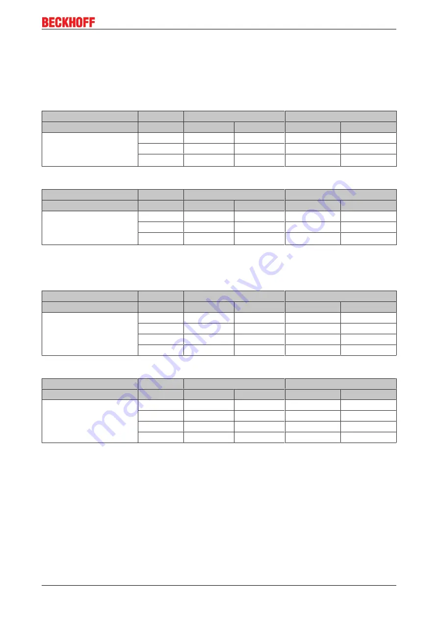
For complete evaluation, the analog input terminals occupy addresses in the input and output process
image. Control and status bytes can be accessed.
Complete evaluation in Intel format
Default mapping for CANopen, CANCAL, DeviceNet, ControlNet, Modbus, RS232 and RS485 coupler
Address
Input data
Output data
Requirements
Word offset High byte
Low byte
High byte
Low byte
Complete evaluation: any
Motorola format: no
Word alignment: no
0
DataIN1 D0
SB1
DataOUT1 D0
CB1
1
SB2
DataIN1 D1
CB2
DataOUT1 D1
2
DataIN2 D1
DataIN2 D0
DataOUT2 D1
DataOUT2 D0
Complete evaluation in Motorola format
Address
Input data
Output data
Requirements
Word offset High byte
Low byte
High byte
Low byte
Complete evaluation: any
Motorola format: yes
Word alignment: no
0
DataIN1 D1
SB1
DataOUT1 D1
CB1
1
SB2
DataIN1 D0
CB2
DataOUT1 D0
2
DataIN2 D0
DataIN2 D1
DataOUT2 D0
DataOUT2 D1
Complete evaluation in Intel format with word alignment
Default mapping for Lightbus, EtherCAT and Ethernet coupler as well as Bus Terminal Controllers (BCxxxx,
BXxxxx)
Address
Input data
Output data
Requirements
Word offset High byte
Low byte
High byte
Low byte
Complete evaluation: any
Motorola format: no
Word alignment: yes
0
reserved
SB1
reserved
CB1
1
DataIN1 D1
DataIN1 D0
DataOUT1 D1
DataOUT1 D0
2
reserved
SB2
reserved
CB2
3
DataIN2 D1
DataIN2 D0
DataOUT2 D1
DataOUT2 D0
Complete evaluation in Motorola format with word alignment
Address
Input data
Output data
Requirements
Word offset High byte
Low byte
High byte
Low byte
Complete evaluation: any
Motorola format: yes
Word alignment: yes
0
reserved
SB1
reserved
CB1
1
DataIN1 D0
DataIN1 D1
DataOUT1 D0
DataOUT1 D1
2
reserved
SB2
reserved
CB2
3
DataIN2 D0
DataIN2 D1
DataOUT2 D0
DataOUT2 D1
Key
Complete evaluation: In addition to the process data, the control and status bytes are also mapped in the
address space.
Motorola format: Motorola or Intel format can be set.
Word alignment: To ensure that the address range of the words always begins on a word boundary, empty
bytes are inserted into the process image.
SB n: status byte n (appears in the input process image)
CB n: control byte n (appears in the output process image)
DataIN n D0: input word n, low-order data byte
DataIN n D1: input word n, high-order data byte
DataOUT n D0: output word n, low-order data byte
DataOUT n D1: output word n, high-order data byte


