Product overview
2.4
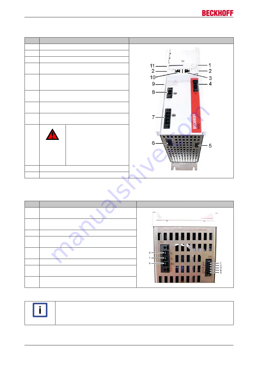
General overview
No.
Name
1
Navigation rocker
2
Labelling field
3
X05 - socket for EtherCAT output
4
X03 – power supply 24 V DC
Input
5
X52 - connection of the temperature monitor
and the fan of the
external brake resistor
6
X51 - connection of the external brake
resistor
7
X01 – mains supply
100 – 480 V
8
X02 – DC link output
(890 V DC voltage).
9
DANGER
Max. voltage 890 V DC at the
DC link terminals (X02). Once
the device has been switched
off dangerous voltage will still
be present for a further 15
minutes. The device is safe
once the voltage has fallen
below 50 V.
10
X04 - socket for EtherCAT input
11
Display
2.5
Pin strip assignment of X51 and X52
No.
Name
1
T-
= input of the temperature measurement
sensor of the external brake resistor
2
T+
= input of the temperature measurement
sensor of the external brake resistor
3
PE
= protective conductor
4
F-
= output to the fan controller
of the external brake resistor
5
F+
= output to the fan controller
of the external brake resistor
6
PE
= protective conductor
7
B-
= output to the controller of
the external brake resistor
8
B+
= output to the controller of
the external brake resistor
Please refer to the servo drive ‘Startup’ manual for the pin assignments of the remaining inputs and outputs.
Note
Temperature rise in the external brake resistor
The temperature rise of the external brake resistor should be monitored continuously via
temperature contacts (1) and (2).
AX5000 Brake module AX5021
6
Version: 1.3


