background image

24

Assembly and Operating Instructions

9b)

9a)

9c)

10)

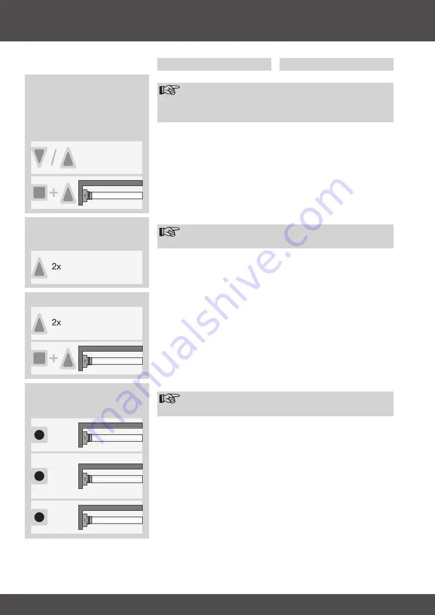
10) Learning additional transmitters

Note
In addition to the master transmitter, up to 15 transmitters can be 

learnt into the tubular drive system.

Press. the. learn. button. of. the. master.
transmitter.programmed.in.3).for.3.sec-
onds.

The.tubular.drive.makes.a.“clack”.sound.
to.confirm.

Now. press. the. learn. button. of. a. new.
transmitter. which. is. unknown. to. the.
tubular. drive. for. 3. seconds.. In. doing.
so,.the.tubular.drive.goes.into.the.pro-
gramme.mode.for.a.new.transmitter.for.
3.minutes.

The.tubular.drive.makes.a.“clack”.sound.
to.confirm.

Now.press.the.learn.button.of.the.trans-
mitter.to.be.programmed.for.a.further.3.
seconds.

The.tubular.drive.makes.a.“clack-clack”.
sound.to.confirm.
The. new. transmitter. has. been. pro-
grammed.

9) Ventilation position

Note
This function is used to move your roller shutters from the lower 

end limit upwards in order to open the ventilation slats. The ven-

tilation position can only be set after the two end limits have been 

set.

9a) Setting the ventilation position

Adjust.the.shutter.into.the.desired.ven-
tilation.position.

First. press. and. hold. the. STOP. button..
Within.3.seconds.also.press.the.UP.but-
ton.and.keep.both.buttons.pressed.

The.tubular.drive.makes.a.“clack”.sound.
to.confirm.
The. ventilation. position. has. been.
stored.

9b) Adjusting the shutters into the ventilation position

Note
The shutters move into the ventilation position from the lower end 

limit.

Press. the. UP. button. twice. within. one.
second.

The.shutter.curtain.moves.into.the.ven-
tilation.position.

9c) Deleting the ventilation position

Adjust. the. shutter. into. the. ventilation.
position.

First. press. and. hold. the. STOP. button..
Within.3.seconds.also.press.the.UP.but-
ton.and.keep.both.buttons.pressed.

The.tubular.drive.makes.a.“clack-clack”.
sound.to.confirm.
The. ventilation. position. has. been. de-
leted.

Action

Response

Clack

Clack-Clack

Clack

Clack

Clack-Clack

Содержание P5/16PRF+A1

Страница 1: ...r den Monteur die Elektrofachkraft den Benutzer Bitte entsprechend weiterleiten Diese Anleitung ist vom Benutzer aufzubewahren GB DE Assembly and Operating Instructions Roller Shutter Drives with integrated radio receiver Important information for Fitters Electricians Users Please forward accordingly These instructions must be kept for future reference ...

Страница 2: ...2 Inhaltsverzeichnis Allgemeines 4 Gewährleistung 4 Sicherheitshinweise 4 Bestimmungsgemäße Verwendung 6 Montage und Inbetriebnahme 6 Technische Daten 14 Was tun wenn 15 ...

Страница 3: ...3 Table of Contents General 16 Warranty 16 Safety Information 16 Intended Use 18 Mounting and installation instructions 18 Technical Data 26 What should you do if 27 ...

Страница 4: ...A1 P9 16PRF A1 und R8 17PRF A1 bis R40 17PRF A1 sind hochwertige Qualitätsprodukte mit vielen Leistungsmerkmalen Einzel Mehrpunkt Gruppen und Zentralsteuerung per Funk Kein Verdrahtungsaufwand zum Schalter oder einer Relaissteuerung Antrieb und Sender frei kombinierbar Installation ohne Anschläge möglich Punkt unten zu Punkt oben Einstellen einer Zwischenposition möglich Einstellen einer Lüftungsp...

Страница 5: ...nal insbesondere Elektro Fachpersonal durchgeführt wer den Beim Betrieb elektrischer oder elektronischer Anlagen und Geräte stehen bestimmte Bauteile z B Netzteil un ter gefährlicher elektrischer Spannung Bei unqualifiziertem Eingreifen oder Nichtbeachtung der Warnhinweise können Körperverletzungen oder Sachschäden entstehen Alle geltenden Normen und Vorschriften für die Elektroinstallation sind z...

Страница 6: ... cm Montage des Rollladenantriebes Achtung Zur Kopplung des Antriebs mit dem angetriebenen Teil dürfen ausschließlich Komponenten aus dem aktuellen Becker Pro duktkatalog für das mechanische Zubehör verwendet wer den Der Monteur muss sich vorher von der erforderlichen Festigkeit des Mauer werks bzw des Rollladenkastens Drehmoment des Antriebs plus Gewicht des Rollladens überzeugen Vorsicht Diese A...

Страница 7: ...eb mit entsprechendem Laufring A und Mit nehmer B Schieben Sie den Rohrantrieb mit dem vormontierten Laufring und Mitnehmer formschlüssig in die Welle ein Achten Sie auf guten Sitz des Laufringes und des Mitnehmers in der Welle Toleranzen der Nutbreiten in verschiedenen Wickelwellen lassen sich bei einigen Mitnehmern durch Drehen des Mitnehmers in eine andere Nutausnehmung ausgleichen Die se Nutau...

Страница 8: ...e den Schalter nach aussen und wieder auf die innere Posi tion zurück Der Rohrantrieb geht für 3 Minuten in Lernbereitschaft 3 Mastersender einlernen Drücken Sie die Einlerntaste innerhalb der Lernbereitschaft für 3 Sekunden Die Quittierung erfolgt durch ein Klack Klack des Rohrantriebes Damit ist der Einlernvorgang beendet Hinweis Falls im Empfänger schon ein Sender eingelernt ist drücken Sie die...

Страница 9: ...ten gedrückt DieQuittierungerfolgtdurchein Klack des Rohrantriebes Die Endlagen sind eingestellt 5c a Punkt unten zu Punkt oben ohne Anschlag b Punkt unten zu Anschlag oben c Hochschiebesicherung in der unteren Endlage zu Punkt oben ohne Anschlag d Hochschiebesicherung in der unteren Endlage zu Anschlag oben zu 5b Punkt unten zu Anschlag oben Fahren Sie die gewünschte untere End lage an Drücken Si...

Страница 10: ...ingestellten Endlagen Hinweis Das Verändern der eingestellten Endlagen kann nur über den Mastersender erfolgen Drücken Sie nun zuerst die Einlerntaste und innerhalb 3 Sekunden zusätzlich die AB Taste für die untere oder die Auf Taste für die obere Endlage und halten Sie die beiden Tasten gedrückt DieQuittierungerfolgtdurchein Klack des Rohrantriebes Die neue Endlage wurde gespeichert 6a Verkürzen ...

Страница 11: ...sten Endlage Vor dem Einstellen der Zwischenposition müssen beide Endlagen einge stellt sein 8a Einstellen der Zwischenposition Fahren Sie den Behang in die ge wünschte Zwischenposition 8b Anfahren der Zwischenposition Hinweis Die Zwischenposition wird aus der oberen Endlage angefahren 8c Löschen der Zwischenposition Fahren Sie den Behang in die Zwischen position Drücken Sie nun zuerst die STOPP T...

Страница 12: ...tersten Endlage soweit wieder Auffahren dass die Lüftungsschlitze ge öffnet werden Vor dem Einstellen der Lüftungsposition müssen beide Endlagen eingestellt sein 9a Einstellen der Lüftungsposition Fahren Sie den Behang in die ge wünschte Lüftungsposition Drücken Sie nun zuerst die STOPP Tas te und innerhalb 3 Sekunden zusätzlich die AUF Taste und halten Sie die beiden Tasten gedrückt DieQuittierun...

Страница 13: ...öscht 12a Rohrantrieb in Lernbereitschaft bringen durch Einschalten der Span nung Der Rohrantrieb geht für 3 Minuten in Lernbereitschaft Jetzt drücken Sie die Einlerntaste des neuen Mastersenders für 10 Sekunden Die Quittierung erfolgt durch ein Klack Klack des Rohrantriebes Der neue Mastersender wurde einge lernt und der alte Mastersender wurde gelöscht Schalten Sie die Spannungsversorgung des Ro...

Страница 14: ...hutzart IP 44 Kl Rohrinnen Ø mm 37 47 Frequenz 915 3 MHz 12b Rohrantrieb in Lernbereitschaft bringen mit dem Funkschalter Der Rohrantrieb geht für 3 Minuten in Lernbereitschaft Jetzt drücken Sie die Einlerntaste des neuen Mastersenders für 10 Sekunden Die Quittierung erfolgt durch ein Klack Klack des Rohrantriebes Der neue Mastersender wurde einge lernt und der alte Mastersender wurde gelöscht Sch...

Страница 15: ...chluss überprüfen 6 5 10 min warten Drehrichtungszuordnung am Rohrantrieb lässt sich nicht einstellen Im Rohrantrieb sind Endlagen gespeichert Rohrantrieb über einen Fahrbefehl starten und über Stopp Befehl stoppen Anschlie ßend mit der PROG und STOPP Taste gesetzte Endlagen löschen Rohrantrieb stoppt wahllos Weiterfahrt in die gleiche Richtung nicht möglich 1 Rohrantrieb hat ein Belastungsanstieg...

Страница 16: ...ower Failure Correction Synchronised Sequence function gives the optical impression of an occupied house Automatic detection of upper limit via intelligent electronic system Automatic detection of lower limit in connection with the anti lifting lock system axle shaft safety catch es Secure anti lifting lock system Slight pressure applied to the shutters prevents them from being raised or forced op...

Страница 17: ...ll as other system parts must always be performed by authorised specialists especially qualified electricians During operation of electrical or electronic equipment and units certain components are subject to a hazardous electrical voltage Physical injuries or damage to property can result in the event of unqualified interventions or failure to comply with the warning notices All applicable standa...

Страница 18: ...m Mounting the roller shutter drive Attention Drives from Becker Antriebe are to be mounted and operated solely with mechanical accessory components shown in the current Becker product catalogue Prior to mounting the fitter must ensure that the masonry and the shutter box are sufficiently robust drive torque plus weight of the shutters Caution These drives may not be operated with conventional swi...

Страница 19: ...rofile tubes Attach a suitable limit ring adapter A and drive adapter B to the tubular drive After having done so slide the drive into the tube so that it engages positively When doing so ensure that the limit ring adapter and drive adapt er fit securely into the tube For some drive adapters the slot width tolerances of different roller tubes can be compensated by turning the drive adapter into an...

Страница 20: ...ion If the switch is already in this position move the button into the outer position and back to the inner position again The tubular drive goes into learn mode for 3 minutes 3 Learning the master transmitter When the drive is in learn mode press the learn button and hold for 3 sec onds The tubular drive makes a clack clack sound to confirm The learn process is complete Note If a transmitter had ...

Страница 21: ...uttons Thetubulardrivemakesa clack sound to confirm The end limits have been set 5c a Lower position to upper position without stopper b Lower position to upper stopper c Anti lifting device at the lower limit to upper position without stopper d Anti lifting device at the lower limit to upper stopper to 5b Lower position to upper stopper Adjust the shutter into the desired lower limit position Fir...

Страница 22: ...e limit position settings Note The limit position settings can only be changed via the master transmitter First press and hold the learn button Within 3 seconds also press the DOWN button for the lower limit or the UP but ton for the upper limit and hold both buttons Thetubulardrivemakesa clack sound to confirm The new limit position has been stored 6a Decreasing the shutter travel distance the de...

Страница 23: ... position can only be set after the two end limits have been set Adjust the shutter curtain into the de sired intermediate position 8b Moving the shutter into the intermediate position Note The shutter moves into the intermediate position from the upper end limit 8c Deleting the intermediate position Adjust the shutter into the intermediate position First press and hold the STOP button Within 3 se...

Страница 24: ...rom the lower end limit upwards in order to open the ventilation slats The ven tilation position can only be set after the two end limits have been set 9a Setting the ventilation position Adjust the shutter into the desired ven tilation position First press and hold the STOP button Within 3 seconds also press the UP but ton and keep both buttons pressed Thetubulardrivemakesa clack sound to confirm...

Страница 25: ...cept the master transmitter have been deleted from the receiver 12a Activating the tubular drive programme mode by switching on the power supply The tubular drive goes into programme mode for 3 minutes Now press the learn button of the new master transmitter for 10 seconds The tubular drive makes a clack clack sound to confirm The new master transmitter has been programmed and the old master trans...

Страница 26: ...e S2 4 Min Protection class IP 44 Min tube diameter mm 37 47 Frequency 915 3 MHz 12b Activating the tubular drive programme mode with the radio switch The tubular drive goes into programme mode for 3 minutes Now press the learn button of the new master transmitter for 10 seconds The tubular drive makes a clack clack sound to confirm The new master transmitter has been programmed and the old master...

Страница 27: ...erly or replace batte ries 5 Check electrical connection 6 Wait 5 10 minutes You are unable to change the axle direction End limits are stored in the tubular drive Start up the tubular drive via a start command and deactivate with a stop command Then delete the end limit settings using the pro gramming and stop buttons Tubular drive has stopped at random and won t run in the given direction 1 Tubu...

Страница 28: ...2010 300 184 0b 11 07 Becker Antriebe GmbH 35764 Sinn Germany ...

Отзывы: