background image

4

Easy Installation

E

E

a

a

s

s

y

y


I

I

n

n

s

s

t

t

a

a

l

l

l

l

a

a

t

t

i

i

o

o

n

n

Easy Installation Steps

The following “Easy Installation” steps are for users accustomed
to the assembly of a computer system. For those individuals
requiring more specific information, please refer to the more
detailed descriptions located within the latter chapters of this
manual.

Note: You must keep your power cable unplugged until the
following installation steps are completed.

Getting Start:

Touch a grounded metal surface to release static electricity
stored in your body before unpacking your motherboard. For
details please refer to Precaution section in Chapter 3.

Install the CPU by correctly aligning the CPU with the Slot as
noted in the motherboard diagram. Once aligned, press down on
the CPU gently but firmly and lock it. Next, install the 3.3 volt
unbuffered SDRAM into the 168 pin DIMMs. See Sec. 3.4.

After completing the above steps, install any expansion

Cards (PCI) into riser card and have the riser card installed
firmly into the slot for riser card on board. See Sec. 3.5.

Plug in all cables included in the package except for the power
cord. Please see Sec. 3.6.

Please recheck all steps to ensure no mistakes have been made
and then plug in the power cord and turn on the power to enter
the BIOS setup, Chapter 4.

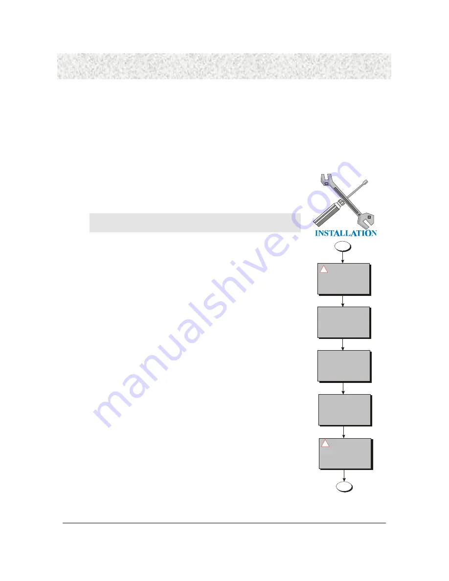
       Release
Static Electricity

Insert CPU &
     RAM

    Install All
Expansion Slots

Set Jumpers of
       CPU

     Couple
Connectors of
   HDD, FDD,...

!

!

Содержание IN810ES

Страница 1: ...1 Intel Slot 1 AGP PCI Motherboard IN810ES IN810S User s Manual ...

Страница 2: ...nternational Inc Responsibility This manual is provided As is with no warranties of any kind either expressed or implied including but not limited to the implied warranties or conditions of this product s fitness for any particular purpose In no event shall we be liable for any loss of profits loss of business loss of data interruption of business or indirect special incidental or consequential da...

Страница 3: ...ovisions of the 1994 Regulations FCC Compliance FCC stands for Federal Communications Commission This product complies with FCC Rules Part 15 and has been tested and complied with the EMI rules by a certified body In normal operation there shall be no harmful interference caused by this device nor shall this devise accept any interference received including interference that may cause undesired op...

Страница 4: ... to Precaution section in Chapter 3 Install the CPU by correctly aligning the CPU with the Slot as noted in the motherboard diagram Once aligned press down on the CPU gently but firmly and lock it Next install the 3 3 volt unbuffered SDRAM into the 168 pin DIMMs See Sec 3 4 After completing the above steps install any expansion Cards PCI into riser card and have the riser card installed firmly int...

Страница 5: ... 1 DIMM Dual Inline Memory Module 18 3 4 2 Installation Procedure 18 3 4 3 DIMM Module Combinations 19 3 5 Expansion Slots 19 3 6 Connectors 20 3 6 1 Primary IDE Connector J28 39 pin block Black 20 3 6 2 Secondary IDE Connector J22 39 pin block White 20 3 6 3 Floppy Drive Connector J29 33 pin block 21 3 6 4 Power Input Connector J20 20 pin block 21 3 6 5 Front Panel connectors J25 15 pin 22 3 6 6 ...

Страница 6: ...K 41 4 5 Advanced Chipset Setup Menu 42 4 5 1 USB Keyboard Legacy Support 42 4 5 2 Display Cache Window Size 42 4 5 3 Display Cache Speed 42 4 5 4 Primary IDE Cable Type 42 4 5 5 Secondary IDE Cable Type 42 4 6 Power Management Setup Menu 43 4 61 Power Management APM 43 4 6 2 Video Power Down Mode 43 4 6 3 Hard Disk Power Down Mode 43 4 6 4 Suspend Time Out Minute 43 4 6 5 Power Button Function 44...

Страница 7: ...hannel 48 4 8 9 OnBoard Midi Port 48 4 8 10 Midi IRQ Select 48 4 8 11 OnBoard Game Port 48 4 8 12 Keyboard PowerOn Function 48 4 8 13 Specific Key for PowerOn 49 4 8 14 Mouse PowerOn Function 49 4 9 Hardware Monitor Setup 49 4 9 1 Current System Temperature 49 4 9 2 Fan 1 Speed 49 4 9 3 Fan 2 Speed 49 4 9 4 CPU VID 50 4 10 Auto Detection IDE HDD 50 4 11 Set User Password 50 4 12 Set Supervisor Pas...

Страница 8: ...ow the installation procedure presented on the Easy Installation Page and refer to the section number following each step if you require more detailed instructions USER MANUAL 1 2 Check Your Device Items The standard package should contain the following items If you find any of these items be missing or damaged please contact your retailer Ø The motherboard Ø 1 IDE ribbon cable Ø 1 floppy ribbon c...

Страница 9: ...nd 83627F HF LPC I O Controller System Memory Ø Two 168 pin DIMM sockets Ø Minimum 16MB up to maximum 512MB Memory Capacity Ø Support PC 100 SDRAM DIMM module Graphic Support Ø GMCHE GMCH0 Integrated H W 3D AGP Graphic Controller 2X Mode Audio and Modem Support Ø ICH Integrated AC97 Controller Ø Three Audio Phone Jacks Line out Line In Mic In MIDI Game Port CD In Modem In and AUX In Ø Aureal AU881...

Страница 10: ...m BIOS Ø 4M bit FWH Integrated Random Number Generator to enhance platform security Ø AMI PCI BIOS with Plug and Play ACPI APM Y2K PC99 and DMI support Ø Bootable from CD ROM supported Green Features Ø Power Management APM 2 1 Ø Additionally with support for ACPI Advanced Configuration and Power Interface feature and On Now your system will become more wise in power management Additional features ...

Страница 11: ...Layout Main Parts FLOPPY FAN 2 PRIMARY IDE USB KEYBOARD MOUSE PRINTER COM1 VGA LVR SLOT DIMM1 DIMM2 ATX POWER CPU GMCHE PCI EXPANSION SLOT FRONT PANEL CONNECTORS FAN 1 AUX IN GAME MIDI AUDIO HEADERS AMR MODEM IN CD IN WOL WOL SECONDARY IDE RING IN FRONT USB CHASSIS SPEAKER ICH ...

Страница 12: ...c 3 6 12 One parallel port Refer to Sec 3 6 12 One VGA port Refer to Sec 3 6 12 One serias port Refer to Sec 3 6 12 One Game MIDI Port Refer to Sec 3 6 12 Line out Refer to Sec 3 6 12 Line in Refer to Sec 3 6 12 MIC in Refer to Sec 3 6 12 Expansion Slots CPU Slot Refer to Sec 3 3 DIMM Sockets Refer to Sec 3 4 1 PCI AMR LVR Slots Refer to Sec 3 5 Power IDE FDD Connectors IDE connectors Refer to Sec...

Страница 13: ...13 Speaker Connector Refer to Sec 3 6 11 Ring In Refer to Sec 3 6 13 Front USB Connector Refer to Sec 3 6 13 CD IN Refer to Sec 3 6 13 AUX IN Refer to Sec 3 6 13 MODEM IN Refer to Sec 3 6 13 CLR CMOS PWD Refer to Sec 3 6 5 SAFE Mode Refer to Sec 3 6 5 ...

Страница 14: ... grounded anti static surface component side up Immediately inspect the board for damage Due to shifting during shipping it is suggested that the installer press down on the entire socket ICs to ensure they are properly seated Do this only with the board placed on a firm flat surface 4 During configuration and installation touch a grounded surface frequently to discharge any static electrical char...

Страница 15: ...pages the triangle s mark stands for pin 1 of connectors Slots Connectors List J17 PCI 1 J23 RING IN J16 PCI 2 J31 SPDIF J15 PCI 3 J11 AUX IN J22 Secondary IDE IDE 2 J12 MODEM IN J28 Primary IDE IDE 1 J6 Game Port J29 Floppy FLP1 J7 Audio Jack J19 Fan 1 J10 CD IN J24 Fan 2 J1 VGA J25 Front Panel Connector J5 Universal Serial Bus Ports J2 PS 2 Keyboard and Mouse Port J8 Parallel Port J4 Serial Port...

Страница 16: ...o the slot firmly and arrange jumper settings carefully presented in sec 3 3 1 3 3 1 Install CPU Please follow the below steps to install your CPU First please ensure the following parts you received with this motherboard One URM Universal Retention Mechanism and four Lock Pins Usually the URM was set on motherboard already 4 Lock Pins Universal Retention Mechanism ...

Страница 17: ...Step 2 Fix the Retention Mechanism to the motherboard with four Lock Pins To insert the Lock Pins into holes to lock them tight and firmly And then unfold the URM Step 3 Push the SEC Cartridge s two locks inward and insert the CPU into Retention Mechanism Press the top of CPU gently but firmly until it is fully inserted Warning It is strongly recommended that a heatsink and CPU cooling fan be used...

Страница 18: ...IMM socket vertically After inserting the DIMM module completely into the socket push up on the socket latches securing the DIMM into place If the pin 1 of the DIMM module does not line up with pin 1 of the socket the DIMM module will not be inserted correctly into the socket Be careful not to misfit the DIMM Module into DIMM sockets in wrong direction This module can be inserted into the socket o...

Страница 19: ...ect DIMM1 32MB DIMM2 64MB Total 32 64 96 MB Select one of the six choices Empty 16MB 32MB 64MB 128MB 256MB in DIMM1 Then repeat in DIMM2 Empty 16MB 32MB 64MB 128MB 256MB to go through your own path 3 5 Expansion Slots This motherboard contains 5 expansion slots including one shared PCI LVR onboard Three 32 bit PCI expansion slots one AMR slot and one LVR slot as shown above All PCI expansion slots...

Страница 20: ...l back panel and additional connectors 3 6 1 Primary IDE Connector J28 39 pin block Black This connector supports two primary channel IDE devices via a ribbon cable When two IDE devices are installed using the primary IDE connector make sure that the second IDE device is set to slave mode as indicated in the device s manual 3 6 2 Secondary IDE Connector J22 39 pin block White This connector suppor...

Страница 21: ...trol three types of floppy drives 1 2 1 44 and 2 88MB or compatible tape drives The connection to the floppy drive is via a header The floppy disk interface includes 48mA drivers and inputs on the drive interface 3 6 4 Power Input Connector J20 20 pin block 1 11 10 20 This connector supports a standard ATX power supply When connecting make sure the lock key matches the hook attached on a power sup...

Страница 22: ... for connecting to front Panel Hard Disk activity LED indicator Sleep Switch 2 pin When the APM Advanced Power Management feature is enabled in the system BIOS and the operating system s APM driver is loaded the system can enter the sleep standby mode in one of the following ways Ø Optional front panel sleep resume button Ø Prolonged system inactivity using the BIOS inactivity timer feature The 2 ...

Страница 23: ...umper please Chassis 2 pin This is for a chassis designed for chassis intrusion detection After market toggle switches may also be installed to the chassis panel or any removable components Two wires should be available from the chassis to connect to this lead When any chassis component is removed the contact should open and the motherboard will record a chassis intrusion event The event can then ...

Страница 24: ... BIOS setup With unlock slot1 processors exceeding the specified multiple is possible through BIOS setup Exceeding the specified multiple may result in hanging during boot up If this occurs enable Safe Mode to force a multiple of 2 in order to enter BIOS setup to correct the problem 3 6 6 Back Panel Connectors Mouse Keyboard USB2 USB1 Parallel port COM1 VGA Line In Line Out Mic In Game MIDI ...

Страница 25: ...onment and improve data transferring capacity True Plug Play This new bus technology will support over 127 different peripherals through a Hub Parallel Port Printer J8 The motherboard includes a parallel port EPP ECP compatible The parallel port is capable of being disabled or remapped to either the secondary LPT address or the primary LPT address through BIOS if another parallel port is installed...

Страница 26: ... VGA port beside the COM1 The Accelerated Graphics Port AGP or A G P is a high performance interconnect targeted at 3D graphical display applications GAME MIDI Port J6 J7 The motherboard integrates a Game MIDI port This port can let you pulg a joystick or MIDI device Game MIDI Audio Port J7 Line in Line out MIC in The motherboard also provides external sound system through a user accessible stereo...

Страница 27: ... wakeup of the computer through a modem Ring In requires an add in modem card with remote wakeup capabilities The remote wakeup header on the add in modem card must be connected to the onboard Ring In header CLR CMOS PWD JP5 This Jumper Choose for clear CMOS Setting allows you to clear password or all CMOS Setting to Default SAFE Mode JP4 Usually Pentium II III processors have locked frequency mul...

Страница 28: ... to connect to this lead When any chassis component is removed the contact should open and the motherboard will record a chassis intrusion event The event can then be processed by software such as LDCM If the chassis intrusion lead is not used a jumper cap must be placed over the pins to prevent unnecessary power loss Front USB Header and Jumper JP1 2 You can use either this Front USB or Back Pane...

Страница 29: ...o subsystem A monaural audio in and audio out signal interface is necessary for telephony applications such as speakerphones fax modems and answering machines Modem IN AUX IN CD IN Green White Black CD IN Header J10 4 pin Black A connector is available for audio input from CD ROM drives AUX IN Header J11 4 pin White Access to the AUX IN connector for audio input from AUX devices ...

Страница 30: ...e system case 4 Connect the power supply cord into an outlet of power supply 5 Connect Monitor signal cable to the system VGA port and the monitor power cord to power outlet 6 Now turn on the monitor and system power After Power on The power LED on the front panel of the system case will light For ATX power supplies the system LED will light when the ATX power switch is pressed The system will the...

Страница 31: ...guring your system using the BIOS Setup 4 1 BIOS Setup The AMI BIOS is immediately activated when you first turn on the computer The BIOS reads system configuration information in CMOS RAM and begins the process of checking the system and configuring it through the power on self test POST When these preliminaries are finished the BIOS seek an operation system on the data storage devices hard drive...

Страница 32: ...xit the Help Window press Esc or the F1 key again 4 1 3 In Case of Problems If after making and saving system changes with Setup you discover that your computer no longer is able to boot the Award BIOS supports an override to the CMOS settings that resets your system to its default configuration The best advice is to alter only settings that you thoroughly understand In particular do not change se...

Страница 33: ... Language Setting Auto Configuration with Optimal Settings Auto Configuration with Fail Safe Settings Save Settings and Exit Exit Without Saving Standard CMOS setup for changing time date hard disk type etc ESC Exit Sel F2 F3 Color F10 Save Exit Figure 1 Main Menu Following is a brief summary of each Setup category Standard CMOS Options in the original PC AT compatible BIOS Advanced CMOS Setup AMI...

Страница 34: ...options to a complete set of default settings when you choose this option Save Settings and Exit Save settings in nonvolatile CMOS RAM and exit Setup Exit Without Saving Abandon all changes and exit Setup 4 3 Standard CMOS Setup Menu In the Standard CMOS Menu Figure 2 you can set the system clock and calendar record disk drive parameters and the video subsystem type and select the type of errors t...

Страница 35: ...about other hard drive types such as SCSI drives NOTE We recommend that you select type AUTO for all drives The BIOS can automatically detect the specifications and optimal operating mode of almost all IDE hard drives When you select type AUTO for a hard drive the BIOS detects its specifications during POST every time the system boots If you do not want to select drive type AUTO other methods of s...

Страница 36: ...ogical Block Addressing During drive accesses the IDE controller Ø Transforms the data address described by sector head and cylinder number Ø into a physical block address significantly improving data transfer rates For drives with greater than 1024 cylinders 4 3 4 Drive A B type Select the correct specifications for the diskette drive s installed in the computer None No diskette drive installed 3...

Страница 37: ...pe are available 1 Match the specifications of your installed IDE hard drive s with the preprogrammed values for drive types 1 through 45 2 Select USER and enter values into each drive parameter field 3 Use the IDE HDD AUTO DECTECTION function in Setup Here is a brief explanation of drive specifications Ø Type The BIOS contains a table of pre defined drive types Each defined drive type has a speci...

Страница 38: ...formation The fields show the total installed random access memory RAM and amounts allocated to base memory extended memory and other high memory RAM is counted in kilobytes KB approximately one thousand bytes and megabytes MB approximately one million bytes RAM is the computer s working memory where the computer stores programs and data currently being used so they are accessible to the CPU Moder...

Страница 39: ...4k Shadow 3 0X IDE 0 Floppy CDROM On Disabled Disabled Enabled VGA EGA Setup Disabled Cached Disabled Available Options 2 0x Safe 3 5x 3 0x 3 5x 4 0x 4 5x 5 0x 5 5x 6 0x 6 5x 7 0x 7 5x 8 0x ESC Exit Sel PgUp PgDn Modify F1 Help F2 F3 Color Exit to Main Menu Figure 3 Advanced BIOS Features Setup Menu 4 4 1 CPU Ratio Selction This option sets the CPU frequency ratio The settings are 1 2 1 4 1 5 2 5 ...

Страница 40: ...or jumper on the motherboard must be shorted together to enable PS 2 mouse support 4 4 9 Primary Display This option configures the type of monitor attached to the computer The settings are Mono CGA40x25 CGA80x25 VGA EGA or Absent The Optimal and Fail Safe default settings are VGA EGA 4 4 10 Password Check This option enables password checking every time the system boots or when you run AMIBIOS Se...

Страница 41: ...from ROM to RAM and can be written to or read from cache memory 4 4 13 D000 Shadow 64K These options enable shadowing of the contents of the ROM area named in the option The ROM area not used by ISA adapter cards is allocated to PCI adapter cards The settings are Setting Description Disabled The contents of the video ROM are not copied to RAM Cached The contents of the video ROM area from C0000h C...

Страница 42: ...u 4 5 1 USB Keyboard Legacy Support Set this option to Enabled to enable support for older keyboards device 4 5 2 Display Cache Window Size This option specifies the amount of cache available for the graphics local memory window The settings are 32MB or 64MB The Optimal and Fail Safe default Settings are 32MB 4 5 3 Display Cache Speed This option shows the speed of cache as 133MHz for IN810ES 4 5 ...

Страница 43: ...Sel PgUp PgDn Modify F1 Help F2 F3 Color Exit to Main Menu Figure 6 Power Management Setup Menu 4 61 Power Management APM Set this option to Enabled to invoke the chipset power management and APM Advanced Power Management features 4 6 2 Video Power Down Mode This option specifies the power state that the video subsystem enters when AMIBIOS places it in a power saving state after the specified peri...

Страница 44: ... not receive or transmit data until the computer and applications are fully running thus connection can not be made on the first try Turning an external modem off and then back on while the computer is off causes an initialization string that will also cause the system to power on 4 6 9 Resume On LAN Header Wake On Lane allows your computer to be booted from another computer via a network by sendi...

Страница 45: ... inform AMIBIOS that the operating system can handle plug and Play PnP devices 4 7 2 Clear NVRAM Select Yes to reset Extended System Configuration Data ESCD when you exit Setup if you have installed a new add on and the system reconfiguration has caused such a serious conflict that the operating system can not boot Normally leave this setting No 4 7 3 Primary Graphics Adapter Leave on default sett...

Страница 46: ...s that the specified IRQ line is used on These options allow you to reserve IRQs for legacy ISA adapter cards These options determine if AMIBIOS should remove an IRQ from the pool of available IRQs passed to devices that are configurable by the system BIOS The available IRQ pool is determined by reading the ESCD NVRAM If more IRQs must be removed from the pool the end user can use these options to...

Страница 47: ...C Exit Sel PgUp PgDn Modify F1 Help F2 F3 Color Exit to Main Menu Figure 5 Integrated Peripherals Setup Menu 4 8 1 OnBoard AC 97 Audio This option allows you to enable the onboard Audio control 4 8 2 OnBoard IDE This option allows you to enable the primary IDE channel secondary IDE channel both or disabled them 4 8 3 OnBoard FDC This option allows you to enable the floppy drive controller on the m...

Страница 48: ...otocol to achieve data transfer rates up to 2 5 Megabits per second ECP provides symmetric bidirectional communication 4 8 7 Parallel Port IRQ This option specifies the IRQ used by the parallel port 4 8 8 Parallel Port DMA Channel This option is only available if the setting for the Parallel Port Mode option is ECP It sets the DMA channel used by the parallel port 4 8 9 OnBoard Midi Port This opti...

Страница 49: ...PM 0 RPM 2 00V 2 032 V 1 536 V 3 312 V 5 085 V 11 802 V 11 907 V N A 3 280 V 4 921 V Availabe Options ESC Exit Sel PgUp PgDn Modify F1 Help F2 F3 Color Exit to Main Menu 4 9 1 Current System Temperature This field shows the current system temperature if your computer contains a monitoring system 4 9 2 Fan 1 Speed The onboard hardware monitor can detect the chassis fan speed in rotations pre minute...

Страница 50: ...password and press Enter To abort the process at any time press Esc In the Security Option item in the BIOS Features Setup screen select System or Setup Ø System Enter a password each time the system boots and whenever you enter Setup Ø Setup Enter a password whenever you enter Setup NOTE To clear the password simply press Enter when asked to enter a password Then the password function is disabled...

Страница 51: ...ill automatically set all AMIBIOS Setup options to a complete set of default settings when you choose this option The Fail Safe settings are designed for maximum system stability but not maximum performance Choose the Fail Safe AMIBIOS Setup options if your computer is experiencing system configuration problems 4 15 Save Settings and Exit This feature allows the changes to be made to the CMOS setu...

Отзывы: