


Installation
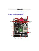
COM1 Port (J6)
The motherboard has one serial port. The electrical characteristics are compliant with the EIA-
232-D Serial Communications Specifications. The serial port may be disabled through the BIOS.
Line-Out (J2)
The motherboard also provides external sound system through an user accessible stereo jack
connector soldered to the PWA. This jack allow the connection of self-amplified speakers.
Mic-In (J1)
The motherboard also provides external sound system through an user accessible stereo jack
connector soldered to the PWA. This jack allow the connection Mic-In voice input.
VGA Port (J4)
This product integrates the AGP function via a VGA port. The monitor hooks up here.
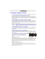
IEEE 1394 Port (J5)
This connector is use for connecting a 1394 device.
3.6.7 Additional Connectors and Headers
Front USB Connector (J19, 10-pin)
The motherboard offers you to hook up front USB ports via chassis. It is always enabled.
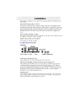
Clear Password Header (JP1, 3-pin)
Clear CMOS. By closing JP1, pins 1 and 2 will clear the CMOS. By closing JP1, pins 2 and 3
will clear password. Under the normal operation, leave JP1, all pin open.
WOR (Wake On Ring) Connector (J21, 2-pin)
This connector is used for resuming from either the APM sleep mode or the ACPI S1 state. It
requires only one call to access the computer. In addition, it detects incoming call similarly for
external and internal modems. It also requires modem interrupt to be unmasked for correct
operation.
System FAN Header (J28, 3-pin)
This connector is used for chassis fan or power fan if needed.
CPU FAN Header (J22, 3-pin)
This connector is used for chassis fan or power fan if needed.
Serial Port 2 Connector (J13, 9-pin)
This connector is for second serial port.
CD-In Header (J10, 4-pin)
A connector is available for audio input from CD-ROM drives.
Line-In/Mic In Header (J5, 5-pin)


