background image


Leak Testing Valves, Hose and Regulator   

1. Turn all grill control knobs to OFF.   

2. Be sure regulator is tightly connected to LP tank.   

3. Completely open LP tank valve by turning OPD hand wheel 

counterclockwise. If you hear a rushing sound, turn gas off 
immediately. There is a major leak at the connection. Correct 
before proceeding by calling Sears for replacement parts at 
1-800-4-MY-HOME®. 

4 .Brush soapy solution onto areas where bubbles are shown in 

picture below: 

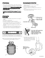
Hold coupling nut and regulator 

as shown for proper connection 

to LP tank valve. 


Never remove threaded 

  orifice at end of valve.   

6. Turn the coupling nut clockwise and tighten to a full stop. The   

regulator will seal on the back-check feature in the LP tank 
valve, resulting in some resistance. An additional one-half to 
three-quarters turn is required to complete the connection. 
Tighten by hand only - do not use tools.   

NOTE:  

If you cannot complete the connection, disconnect regulator 
and repeat steps 5 and 6. If you are still unable to complete the 
connection, do not use this regulator!   
Call 1-800-4-MY-HOME® for an identical replacement part. 

DANGER 

• Do not insert any tool or foreign object into the valve 

outlet or safety relief valve. You may damage the valve 
and cause a leak. Leaking propane may result in 

explosion, fire, severe personal injury, or death. 

5. If “growing” bubbles appear, there is a leak. Close LP tank   

valve immediately and retighten connections. If leaks cannot be 
stopped do not try to repair. Call for replacement   

parts at 1-800-4-MY-HOME®. 

6. Always close LP tank valve after performing leak test by 

turning hand wheel clockwise.   

WARNING 

• 

Outdoor gas appliance is not intended to be installed 
in or on a boat. 

• 

Outdoor gas appliance is not intended to be installed 
in or on an RV. 

• 

Never attempt to attach this grill to the self-contained 
LP gas system of a camper trailer or motor home. 

• 

Do not use grill until leak-tested. 

• 

If a leak is detected at any time, STOP and call the fire 
department. 

• If you cannot stop a gas leak, immediately close   

LP cylinder valve and call LP gas supplier or your fire 
department !   

6 • 146.47468610   

Содержание PG-40522SOL

Страница 1: ...OWNER S MANUAL BBQ Pro 5 Burners gas grill with Stainless Steel lid Product code 47468 0 02236025 9 Item 146 47468610 UPC code 182995001771 Date of purchase ...

Страница 2: ...nsafe practice which if not avoided may result in minor or moderate injury Installation Safety Precautions Please read this User s Manual in its entirety before using the grill Failure to follow the provided instruction can result in seriously bodily injury and or property damage Some parts of this grill may have sharp edges Please wear suitable protective gloves Use grill as purchased only with L...

Страница 3: ...ements Congratulations on making a smart purchase Your new BBQ PRO product is designed and manufactured for years of Expert service by our 10 000 professional repair specialists Unlimited service and no charge for parts and labor on all covered repairs Product replacement up to 1500 if your covered product U S A call 1 800 4 MY HOME door openers water heaters and other major home items in the For ...

Страница 4: ...osition for vapor withdrawal LP Liquefied Petroleum Gas LP Tank Removal Transport And Storage Turn OFF all control knobs and LP tank valve Turn coupling nut counterclockwise by hand only do not use tools to disconnect Lift LP tank wire upward off of LP tank collar then lift LP tank up and off of support bracket Install safety cap onto LP tank valve Always use cap and strap supplied with valve Fail...

Страница 5: ...p and Cap Leak test must be repeated each time LP tank is exchanged or refilled Do not smoke during leak test Do not use an open flame to check for gas leaks Grill must be leak tested outdoors in a well ventilated area away from ignition sources such as gas fired or electrical appliances During leak test keep grill away from open flames or sparks Use a clean paintbrush and a 50 50 mild soap and wa...

Страница 6: ... repeat steps 5 and 6 If you are still unable to complete the connection do not use this regulator Call 1 800 4 MY HOME for an identical replacement part DANGER Do not insert any tool or foreign object into the valve outlet or safety relief valve You may damage the valve and cause a leak Leaking propane may result in explosion fire severe personal injury or death 5 If growing bubbles appear there ...

Страница 7: ... used to clean any of the grill cooking surfaces ensure no loose bristles remain on cooking surfaces prior to grilling It is not recommended to clean cooking surfaces while grill is hot If you notice drip or other hot material dripping from grill determine the cause correct it then clean and inspect valve Keep ventilation openings in cylinder enclosure grill cart free and clear of debris Do not st...

Страница 8: ...om the tray and slide the tray out of the grill Clean the grease drippings from the cup and tray surfaces by washing with mild detergent or nonabrasive cleaner and warm soapy water Wipe dry with a soft nonabrasive cloth Slide the tray back into the grill and replace the cup back into the tray before using the grill again Burner Flame Check Remove cooking grates and heat diffusers Light burners tur...

Страница 9: ... build nests and lay eggs in the grill s venturi tube s obstructing the flow of gas to the burner The backed up gas can ignite in the venturi behind the control panel This is known as a flashback and it can damage your grill and even cause injury To prevent flashbacks and ensure good performance the burner and venturi assembly should be removed from the grill and cleaned before use whenever the gr...

Страница 10: ...perature Place food over over unlit burner s How To Tell If Meat Is Grilled Thoroughly Meat and poultry cooked on a grill often browns very fast on the outside Use a meat thermometer to be sure food has reached a safe internal temperature and cut into food to check for visual signs of doneness Whole poultry should reach 180 F breasts 170 F Juices should run clear and flesh should not be pink Hambu...

Страница 11: ...5 40800023 E06 Side Lower Rail 2 52200064 B04 Main burner 4 40700125 E07 Axle Rod 1 408D00125 B05 Igniter Wire Ignition Burner 1 52200035 E08 Wheel 2 40800124 B06 Burner 1 52200034 E09 Hex Nut 3 110011 B07 Gas Valve Side Burner 1 40900209 E10 Flat Washer 3 110018 B08 Regulator 1 408D00115 E11 Cotter Pin 11 110050 B09 Gas Valve Main burner 5 40900205 E12 Back Rail 1 52200074 B10 Manifold Main burne...

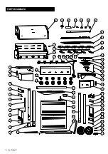
Страница 12: ...A01 A02 A03 A04 A05 B01 B02 A06 B03 B04 A07 B10 B11 B13 B07 B06 B05 B08 B09 B14 B15 B16 E02 E03 E04 E05 E06 E07 E13 E14 E15 E16 E17 E18 E12 E19 E01 E21 E22 E23 E24 E05 E06 E20 E25 E26 D09 E27 E08 E09 E11 B12 E01 E10 12 146 47468610 PARTS DIAGRAM ...

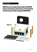
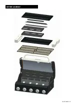
Страница 13: ...ASSEMBLY NOTICE Once you have unpacked the grill according to the STOP SHEET instructions check all grill parts against the pictures on this and the following two pages If any parts are missing or damaged call 1 888 287 0735 ...

Страница 14: ...14 146 47468610 BEFORE ASSEMBLY ...

Страница 15: ...146 47468610 15 BEFORE ASSEMBLY ...

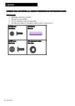
Страница 16: ...ls Required Adjustable wrench not provided Screwdriver not provided 7 16 Combination wrench not provided The following hardware is provided in blister pack for convenient use M4X10 screw Qty 58 pcs AAA Battery Qty 1 pc M6X13 screw Qty 16 pcs M6 compression washer Qty 4 pcs 16 146 47468610 ...

Страница 17: ...of Side Lower Rail to the leg tighten the screws C Attach Side Panel to leg with 2 M4 10 Screws as shown C Install 4 M4 10 Screws as shown to the leg marked 5B Do not fully tighten the screws at this time B Attach another end of Side Upper Rail Side Lower Rail and Side Panel to the 5B Leg tighten the screws Install 2 M4 10 Screws as shown to the Side Panel Install 1 M4 10 Screws as shown to anothe...

Страница 18: ...f Side Lower Rail to the leg tighten the screws C Attach Side Panel to leg with 2 M4 10 Screws as shown C Install 4 M4 10 Screws as shown to the leg marked 5D Do not fully tighten the screws at this time B Attach another end of Side Upper Rail Side Lower Rail and Side Panel to the 5D Leg tighten the screws Install 2 M4 10 Screws as shown to the Side Panel Install 1 M4 10 Screws as shown to another...

Страница 19: ... tighten the screws at this time A Attach Bottom Shelf to Right Leg Frame with 3 M4 10 Screws Do not tighten these screws A Install 4 M4 10 Screws as shown to Left Frame Do not fully tighten the screws at this time B Attach Bottom Shelf to Left Leg Frame with 3 M4 10 Screws Do not tighten these screws B Bottom Shelf Right Side Frame 5C 5D ...

Страница 20: ...Frame fully tighten the screw b tighten another end of the Support Bar to the frame with 2 M4 10 Screws as shown c Attach the Left Drip Tray Support to the Left Frame fully tighten the screw tighten another end of the Left Drip Tray Support Bar to the frame with 2 M4 10 Screws as shown Attach remaining Screw to the Front Panel and Bottom Shelf with 1 M4 10 Screws the middle screw hole d 20 146 474...

Страница 21: ...tom Shelf and Four Legs with 4 M6 13 Screws as shown A Tap both Leg Extenders onto Left Leg B Remove washer nut hitch pin from axle rod Insert Axle Rod through Wheels and Right Leg Frame Reattach with washer nut and hitch pin C Stand cart upside fully tighten 6 M4 10 Screws in step 3A and 3B attach the Tank Baffle with 2 M4 10 Screws D B C ...

Страница 22: ...aterial from regulator hose side burner valve and igniter wire Pull hose and igniter wire out to side of grill head Carefully lower the grill head onto the cart Make sure the regulator hose and igniter wire are hanging outside the cart Line up control panel with front panels Attach head to cart with 4 M6 13 Screws from sides M6X13 screw Qty 4 pcs ...

Страница 23: ... Temperature Gauge through Lid and tighten with the Wing Nut Left Side Shelf 1 Install the 2 M6 13 Screws on the left of Firebox Do not fully tighten the screws Place on the Left Side Shelf bracket and pull to its position M6X13 screw Qty 2 pcs ...

Страница 24: ...Screws and 2 M6 compression washers A Align the Side Fascia and Control Panel attach them from outside to inside of Firebox with 1 M4 10 Screws Attach Left Side Shelf to Control Panel with 1 M4 10 Screws fully tighten the 2 M6 13 Screws in above step as shown B M4X10 screw Qty 2 pcs M6X13 screw Qty 2 pcs M6 compression washer Qty 2 pcs A B ...

Страница 25: ...146 47468610 25 Right Side Shelf 1 Install the 2 M6 13 Screws on the Right of Firebox Do not fully tighten the screws Place on the Right Side Shelf bracket and pull to its position M6X13 screw Qty 2 pcs ...

Страница 26: ...ews and 2 M6 compression washers A Align the Side Fascia and Control Panel attach them from outside to inside of Firebox with 1 M4 10 Screws Attach Left Side Shelf to Control Panel with 1 M4 10 Screws fully tighten the 2 M6 13 Screws in above step as shown B M4X10 screw Qty 2 pcs M6X13 screw Qty 2 pcs M6 compression washer Qty 2 pcs A B ...

Страница 27: ... to secure bezel to fascia G Place side burner tube over the valve making sure that valve is inside side burner tube H Push control knob onto side burner valve stem I Reattach side burner to side burner shelf with the 2 previously removed screws Replace side burner grate J Remove igniter cap and nut pre assembled to the electronic ignition module and use them to attach ignition module to the right...

Страница 28: ...11 28 146 47468610 G H I J H K L ...

Страница 29: ...sers will fit in firebox in either direction Fit tabs in firebox front through slots in Diffusers tips Fit diffusers tips between tabs in Firebox Rear Place Cooking Grates onto grate rests at front and rear of Firebox Insert warming rack into brackets at top of Firebox with Curved edge to front as shown ...

Страница 30: ...ket on cart right leg Insert hose into bracket and replace cotter and pin Hang Drip Cup Clip from bottom of drip tray and insert Drip Tray into bottom of Firebox from back of cart Fit Drip Cup into Drip Cup Clip B Place LP tank into hole in bottom shelf with tank collar opening facing to side as shown C Raise tank holder to hold LP tanks securely in place M4X10 screw Qty 4 pcs A B C ...

Страница 31: ...ean swab Reconnect wires or replace electrode wire assembly Replace igniter wire electrode assembly Replace with a new AA size alkaline battery Problem Problem Possible Cause Possible Cause Prevention Solution Prevention Solution EMERGENCIES If a gas leak cannot be stopped or a fire occurs due to gas leakage call the fire department Damaged hose Mechanical failure due to rusting or mishandling Fai...

Страница 32: ...der Reconnect and retry Turn knobs to OFF Turn gas off at LP cylinder Leave lid in position and let fire burn out After grill cools remove and clean all parts Turn knobs to OFF Clean burner and or burner tubes See burner cleaning section of Use and Care Prevention Solution Troubleshooting continued Possible Cause ELECTRONIC IGNITION No spark no ignition noise No spark some ignition noise Sparks bu...

Страница 33: ...CTION II No sparks appear at any electrodes when control knob turned to HI noise can be heard from spark module Are output connections on and tight Remove and reconnect all output connections at module and electrodes SECTION III Sparks are present but not at all electrodes and or not at full strength Output lead connections not connected Electrical arc between output wires and grill frame Weak bat...

Страница 34: ...MANUAL DE PROPIETARIO BBQ Pro 5 quemadores parrilla de gas con tapa de acero inoxidable Código de producto 47468 0 02236025 9 Item 146 47468610 Código de UPC 182995001771 Fecha de compra ...

Страница 35: ...rla en ningún otro lugar Cualquier modificación puede poner en peligro su seguridad IMPORTANTE Esta parrilla es para uso exclusivo al aire libre y no está destinada a ser instalada en o sobre vehículos de recreo o embarcaciones NOTA PARA EL INSTALADOR Deja este manual del usuario con el cliente después de la entrega y o instalación NOTA A LOS CONSUMIDORES Deja este manual del usuario en un lugar c...

Страница 36: ... o de mano de obra dentro del plazo de un año desde la fecha de compra llame al 1 800 4 MY HOME ón gratuita o el cambio si la reparación resulta imposible de realizar LAS PARRILLAS DE COCCION Y DIFUSORES DE CALOR 1 año de garantía no cubre caídas cincelado rayar o dañar la superficie PIEZAS DE ACERO INOXIDABLE 1 año de garantía contra la perforación no cubre problemas cosméticos como arañazos o co...

Страница 37: ...para extraer el vapor Remoción transporte y almacenamiento del tanque de gas propano CIERRE todas las perillas de control y la válvula del tanque Gire la tuerca de unión en sentido contrario a las agujas del reloj a mano solamente no use herramientas para desconectarla Afloje el tornillo del tanque que se encuentra por debajo de el estante inferior y luego levante el tanque y sáquelo del carro Ins...

Страница 38: ...olumétrica Salida tipo 1 con rosca exterior Válvula de seguridad Tira y tapa Se debe efectuar la prueba para detectar fugas cada vez que se cambie o se recargue el tanque No fume durante la prueba para detectar fugas No use una llama al descubierto para comprobar si el tanque tiene fugas La prueba para detectar fugas de la parrilla se debe efectuar al aire libre en un área bien ventilada alejada d...

Страница 39: ...4 MY HOME PELIGRO No introduzca ninguna herramienta ni ningún objeto extraño en la salida de la válvula ni en la válvula de seguridad Puede dañarla y causar una fuga Las fugas de gas propano pueden causar explosiones incendios lesiones graves o la muerte 5 Si aparecen burbujas que aumentan de tamaño existe una fuga Cierre de inmediato la válvula del tanque de gas y vuelva a apretar las conexiones ...

Страница 40: ...r un sonido zumbante o sibilante durante su uso Esto no afectará la seguridad ni el uso de la parrilla Utilice solamente el regulador de presión y el montaje de manguera provistos de esta parrilla El regulador de presión del reemplazo y los montajes de manguera deben ser especificados o provisto cerca Si tiene un problema con la parrilla lea la sección de Resolución de problemas Si el regulador se...

Страница 41: ... limpiar las parrillas Después de la limpieza rejas secos a fondo con una toalla de tela Rejillas Coat con aceite vegetal o aerosol antiadherente para cocinar Coloque las rejillas en la parrilla Comience parrilla y levante lentamente la temperatura a 350 400 F rejillas de calor durante una hora Apague la parrilla y las rejillas permiten que se enfríen completamente antes de usar de nuevo Limpieza ...

Страница 42: ...el quemador para detectar daños algunos orificios pueden alargarse debido al desgaste normal y a la corrosión Si observa grietas u orificios grandes cambie el quemador 9 Vuelva a colocar cuidadosamente los quemadores Fije los quemadores a los soportes de la cámara de combustión 10 Vuelva a colocar los tubos de arrastre y fije los quemadores Cambie los reguladores de llama y las parrillas de cocció...

Страница 43: ...uficiente temperatura de cocción Cómo saber cuándo las carnes están bien cocidas El exterior de las carnes y las piezas de ave preparadas a la parrilla a menudo se dora rápidamente Use un termómetro para carnes para verificar que los alimentos alcancen una temperatura interna segura y corte la carne para verificar visualmente si ya está lista La temperatura de las aves enteras debe alcanzar 180 F ...

Страница 44: ...dor 1 408D00115 E11 Chaveta 11 110050 B09 Válvula de gas quemador principal 5 40900205 E12 Rail Volver 1 52200074 B10 Múltiple quemador principal 1 50300041 E13 Bandeja de goteo 1 52200031 B11 Firebox 1 52200018 E14 goteo Copa 1 40800026 B12 Llama Carry Over Tubo 4 50300024 E15 Goteo Copa videoclip 1 40800131 B13 Caucho de silicona parachoques Firebox 2 40700099 E16 Panel frontal 2 52200075 B14 Pa...

Страница 45: ...1 A02 A03 A04 A05 B01 B02 A06 B03 B04 A07 B10 B11 B13 B07 B06 B05 B08 B09 B14 B15 B16 E02 E03 E04 E05 E06 E07 E13 E14 E15 E16 E17 E18 E12 E19 E01 E21 E22 E23 E24 E05 E06 E20 E25 E26 D09 E27 E08 E09 E11 B12 E01 E10 DIAGRAMA DE PARTES 146 47468610 45 ...

Страница 46: ...A Aviso Una vez desempaquetado la parrilla según las instrucciones de detener la hoja revise que todo parrilla partes contra los cuadros sobre ésta y las siguientes dos páginas Si alguna pieza está dañada o falta llame al 1 888 287 0735 ...

Страница 47: ...146 47468610 47 ANTES DE LA ASAMBLEA ...

Страница 48: ...48 146 47468610 ANTES DE LA ASAMBLEA ...

Страница 49: ...LOWING PAGES Tools Required Adjustable wrench not provided Screwdriver not provided 7 16 Combination wrench not provided The following hardware is provided in blister pack for convenient use M4X10 screw Qty 58 pcs AAA Battery Qty 1 pc M6X13 screw Qty 16 pcs M6 compression washer Qty 4 pcs ...

Страница 50: ...ierna apriete los tornillos C Coloque el panel lateral de la pierna con 2 M4 10 Tornillos como se muestra C Instalar 4 M4 10 Tornillos como se muestra a la pata marcada 5B No apriete los tornillos en este momento B Conecte el otro extremo de la parte superior del carril lado inferior del carril y el panel lateral a la 5B Pierna apriete los tornillos Instale 2 M4 10 Tornillos como se muestra en el ...

Страница 51: ...nillos y conectar con otro 1 M4 10 Tornillo C Coloque el panel lateral de la pierna con 2 M4 10 Tornillos como se muestra C Instalar 4 M4 10 Tornillos como se muestra a la pata marcada 5D No apriete los tornillos en este momento B Conecte el otro extremo de la parte superior del carril lado inferior del carril y el panel lateral a la 5D Pierna apriete los tornillos Instale 2 M4 10 Tornillos como s...

Страница 52: ...llos en este momento A Adjuntar estante inferior al cuadro derecho Pierna con 3 M4 10 Tornillos No apriete los tornillos A Instalar 4 M4 10 Tornillos como se muestra al cuadro izquierdo No apriete los tornillos en este momento B Adjuntar estante inferior al cuadro izquierdo Pierna con 3 M4 10 Tornillos No apriete los tornillos B Estante inferior Marco lateral derecho 5C 5D ...

Страница 53: ...etamente el tornillo apriete el otro extremo de la barra de soporte a la estructura con 2 M4 10 Tornillos como se muestra C Coloque la izquierda goteo soporte de la bandeja para el cuadro izquierdo apriete completamente el tornillo apriete el otro extremo del soporte de la bandeja Bar Izquierda goteo a la estructura con 2 M4 10 Tornillos como se muestra Atornille el panel frontal y estante inferio...

Страница 54: ...uestra A Toque en tanto la pierna extensores en el pie derecho de la pierna B Retire la tuerca lavadora y pasador de enganche de la varilla del eje de inserción Eje Varilla través de ruedas y la pierna Correcto del marco Vuelva a conectar con la arandela tuerca y pasador de enganche C parese carrito de cabeza Totalmente Apriete 6 M4 10 Tornillos en el paso 3A y 3B conecte el tanque del bafle con 2...

Страница 55: ...la del quemador lateral y el cable de encendido Tire de la manguera y el cable de encendido a lado de la cabeza de la parrilla Baje con cuidado la cabeza de la parrilla sobre el carrito Asegúrese de que la manguera del regulador y el cable de encendido están colgando fuera del carrito Alinee el panel de control con paneles frontales Coloque la cabeza a la cesta con 4 M6 13 Tornillos de los lados M...

Страница 56: ...ura a través de la tapa y apriete con la Tuerca de mariposa Left Side Shelf 1 Instale el 2 M6 13 Tornillos de la izquierda del Firebox No apriete completamente los tornillos Coloque en el soporte del lado izquierdo del estante y saque a su posición M6X13 Tornillos Qty 2 pcs ...

Страница 57: ...3 Tornillos y 2 arandelas de compresión M6 A Alinee la fascia y el Control Panel lateral adjuntarlos del exterior al interior de la cámara de combustión con 1 M4 10 Tornillos Adjuntar Left Side Shelf a Panel de control con 1 M4 10 Tornillos apriete los 2 M6 13 Tornillos en el paso anterior como se muestra B M4X10 Tornillos Qty 2 M6X13 Tornillos Qty 2 M6 compression washer Qty 2 pcs A B ...

Страница 58: ...610 Right Side Shelf 1 Instale el 2 M6 13 Tornillos sobre el derecho de Firebox No apriete completamente los tornillos Coloque en el soporte del lado derecho del estante y saque a su posición M6X13 Tornillos Qty 2 ...

Страница 59: ...ornillos y 2 arandelas de compresión M6 A Alinee la fascia y el Control Panel lateral adjuntarlos del exterior al interior de la cámara de combustión con 1 M4 10 Tornillos Adjuntar Left Side Shelf a Panel de control con 1 M4 10 Tornillos apriete los 2 M6 13 Tornillos en el paso anterior como se muestra B M4X10 Tornillos Qty 2 M6X13 Tornillos Qty 2 M6 compression washer Qty 2 pcs A B ...

Страница 60: ...lateral Coloque sobre la válvula asegurándose de que la válvula es de tubo quemador lateral interior H perilla de control de empuje en el vástago de la válvula del quemador lateral I Vuelva a colocar el quemador lateral en el lado repisa del quemador con los 2 tornillos retirados previamente Vuelva a colocar la rejilla del quemador lateral J Retire la tapa del encendedor y la tuerca de pre ensambl...

Страница 61: ...11 146 47468610 61 G H I J H K L ...

Страница 62: ... de ajuste frente cámara de combustión a través de ranuras en consejos Difusores difusores consejos ajuste entre pestañas en Firebox posterior Coloque las parrillas de cocción sobre sus rejilla descansa en el frente y la parte posterior de la cámara de combustión Inserte la rejilla para calentar en los soportes en la parte superior de la cámara de combustión con el borde curvado hacia adelante com...

Страница 63: ...era en el soporte y vuelva a colocar la chaveta y el pasador Cuelgue goteo Copa videoclip desde el fondo de la bandeja de goteo e inserte la bandeja de goteo en el fondo de la cámara de combustión de la parte posterior de la compra Ajuste goteo Copa en Goteo Copa videoclip B tanque Place LP en el orificio de la repisa inferior con la apertura de cuello del tanque frente a otro como se muestra C Le...

Страница 64: ...a grasa y de toda otra superficie Manguera dañada Falla mecánica debido a la oxidación o al mal uso Falla de la válvula del cilindro debida a mal uso o a falla mecánica Instalación inadecuada la conexión no está bien apretada falla de la junta de caucho Fuego en la sección del tubo del quemador debido a un bloqueo Demasiada grasa acumulada en la zona del quemador PROBLEMAS DE ELECTRICIDAD EMERGENC...

Страница 65: ...ncender chimeneas Lea la sección de limpieza de Uso y cuidado Limpie los quemadores y el interior de la parrilla cámara de combustión Desgrase la carne antes de cocinarla a la parrilla Ajuste baje la temperatura según corresponda Las boquillas desgastadas no tienen suficiente agarre para conectarse a la válvula Comuníquese con otro vendedor de gas Un quemador no se enciende desde el quemador otra ...

Страница 66: ...tán conectadas y bien hechas las conexiones de salida Retire y vuelva a hacer todas las conexiones de salida en el módulo y en los electrodos SECCIÓN III Hay chispas pero no en todos los electrodos y o no a plena potencia Las conexiones del cable de salida no están bien hechas El arco de la parrilla se forma lejos del de los quemador es Pila débil Los electrodos están húmedos Los electrodos están ...

Страница 67: ......
Отзывы: