background image

6.1

      Synchronizing 720644801 7 day Wireless 

          & 720644901 24h Wireless 

6.0  Manual Sync. Function 

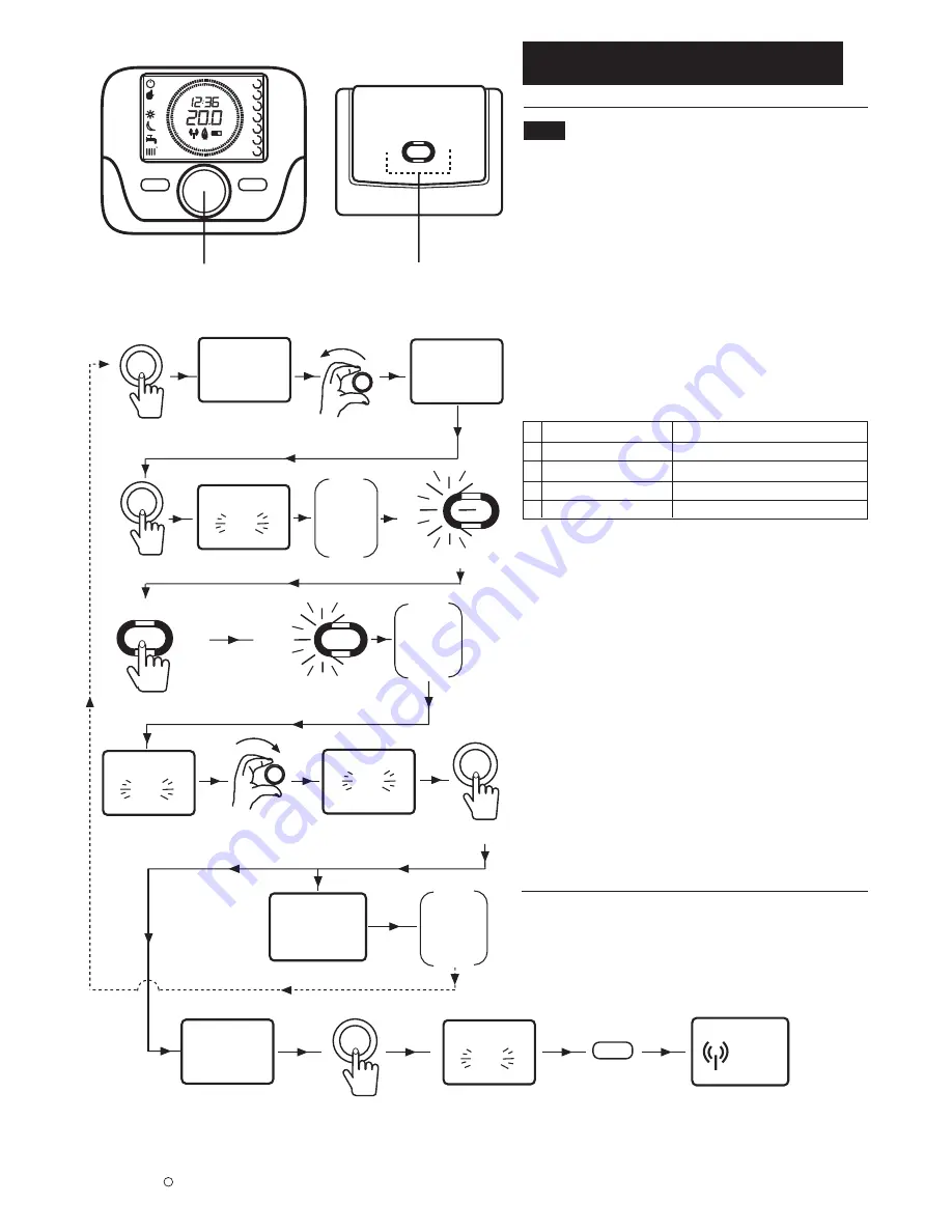
The Programmer & Room Sensor and the Receiver can be 
synchronized using the method shown in Fig. 18 as follows:

1. Start by setting up the Programmer & Room Sensor.
Press and hold the Selector Button (Fig. 16) for approx. 6 
seconds. ‘HC 1’ will be seen on the display.

2. Rotate the Selector Button until ‘SnC OFF’ is seen in the 
display.

3. Press the Selector Button and ‘OFF’ will flash. This display 
will only remain on the screen for approximately 60 
seconds.

4. Now set up the Receiver. LED ‘L1’ will be flashing. Fig. 
18. One of the following conditions will be seen. 

1   One flash every 2 secs 

Boiler and Controller Synchronized.

  2   Two flashes every 2 secs 

Communication error

  3   Three flashes every 2 secs 

No communication yet

  4   Flash for 1sec 


NA for Sync

  5   1 sec flash every 1 sec 

Synchronization initialisation

See Fig. 27 for detailed description

5. If one flash is seen every 2 seconds, the boiler and 
Programmer & Room Sensor are already synchronized. 
Return to the Programmer & Room Sensor and press 
Menu twice to exit the Synchronization menu. 

8

Baxi Heating UK Ltd 2011

c

AUTO

1

7

6

5

4

3

2

MODE

MENU

24

21

18

15

12

3

6

9

°C

Hold for 6 seconds

Fig. 16. Programmer & Room Sensor
Selector Button

Fig. 18. Manual Sync Process Diagram

Fig. 17. Receiver LED Display
& Button

L1

L2

L1

L2

HC

1

SnC

OFF

SnC

End

Err

L1

Rapid Flash

Press & 

hold until 

slow flash

L1

Slow Flash

SnC
ON

OFF

SnC

OFF

SnC

OFF

Return

to

Controller

Go to

Receiver

Unit

Reposition

&

Retry

6. If L1 shows 3 flashes every 2 seconds the units are not 
synchronized. Press and hold the Receiver Button until 
the rapid flash at L1 changes to a slow flash. 

7. Return to the Programmer & Room Sensor where
‘SnC OFF’ will be flashing. Rotate the Selector Button 
until ‘SnC ON’ is seen. Press the Selector Button and 
the display shows 4, 3, 2, 1 counting down. When this 
process is complete, the unit will display ‘End’ if 
synchronization has been successful. Press the Selector 
Button to return to the ‘SnC OFF’ screen then press 
MENU to escape.

8. If Error 85 is still displayed, the unit hasn’t synchronized 
correctly. Return to the beginning and repeat the process.

. . . 4,  3,  2,  1

MENU

Содержание 720644701

Страница 1: ...Please keep these instructions in a safe place If you move house please hand them over to the next occupier Part No 720644701 7 day Wired Digital Programmer Room Sensor Part No 720644801 7 day Wireless Digital Programmer Room Sensor Part No 720644901 24hr Wireless Digital Programmer Room Sensor 720644801 shown B ...

Страница 2: ... Temperature Settings 11 10 0 Setting the Time Day 12 11 0 Setting Central Heating Domestic 13 Hot Water 12 0 Programmer Room Sensor 14 Parameter Codes 13 0 Error Codes 15 Page Baxi Heating UK Ltd 2011 c Programmer Room Sensor 7 day Wired Programmer Room Sensor 7 day Wireless Programmer Room Sensor 24hr Wireless Receiver Batteries AA LR6 Fixing Screws Rawlplugs Instructions 720644701 720644801 720...

Страница 3: ...oiler will run the Hi COMFORT settings during a heating demand and the Lo REDUCED setting for overnight periods or times when the property is left unoccupied 1 The units require 2 AA type alkaline batteries Supplied Installation of the batteries is shown in Fig 12 2 If the battery symbol is seen flashing in the digital display Fig 5 the batteries need replacing See Fig 12 for details 3 The batteri...

Страница 4: ...e Automatic Mode Manual Mode STANDBY MODE MENU 1 1 Press the MENU Button Day of the week 1 MON 7 day only Day of the week selected 7 day only Standby selected Central Heating flashing selected Signal Strength flashing no signal Boiler runs using User defined times Boiler in REDUCED Mode Boiler in COMFORT Mode Press the MODE Button Rotate the Selector Button Press the Selector Button Symbol Meaning...

Страница 5: ...ystem Fig 6 1 Power down the boiler 2 Remove the backplate from the unit by pressing down on the rear tab and easing apart Fig 12 3 Identify a suitable site to locate the Programmer Room Sensor See Fig 8 for guidance on where to locate the unit 4 Use a suitable grade of wire when connecting the Programmer Room Sensor to the boiler A specification of 2 x 0 75mm with a maximum length of 50m should b...

Страница 6: ...ring 6 Connect the other end of the wire to the terminals on the boiler Please refer to the boiler manual for wiring details 7 Fix the Receiver to the wall using the fixings provided and refit the front cover ensuring the correct orientation Fig 11 8 Fit the batteries to the Programmer Room Sensor Fig 12 6 Baxi Heating UK Ltd 2011 c OT OT Fig 9 Receiver Backplate 4 3 Connecting 720644801 7 day Wir...

Страница 7: ...ver and the Programmer Room Sensor will depend on the layout of the house For a typical house a guideline of 3 floors or walls can be used as shown in Fig 13 MODE MENU 24 21 18 15 12 3 6 9 C MODE MENU 24 21 18 15 12 3 6 9 C MODE MENU 24 21 18 15 12 3 6 9 C A B C X Before mounting the Programmer Room Sensor to the wall perform the following test to determine the signal strength Fig 15 1 Press and h...

Страница 8: ...oom Sensor are already synchronized Return to the Programmer Room Sensor and press Menu twice to exit the Synchronization menu 8 Baxi Heating UK Ltd 2011 c AUTO 1 7 6 5 4 3 2 MODE MENU 24 21 18 15 12 3 6 9 C Hold for 6 seconds Fig 16 Programmer Room Sensor Selector Button Fig 18 Manual Sync Process Diagram Fig 17 Receiver LED Display Button L1 L2 L1 L2 HC 1 SnC OFF SnC End Err L1 Rapid Flash Press...

Страница 9: ...nfirm the selection and then Menu to return to the main screen If Menu isn t pressed the display will return to the Main screen after approximately 2 seconds The unit is now in Operating Mode Fig 21 Standby Operating Mode Diagram MODE MENU To Escape or wait 2 secs Confirm Confirm AUTO 1 7 6 5 4 3 2 MODE MENU C Fig 19 Unit in Standby Mode AUTO 1 7 6 5 4 3 2 MODE MENU C Fig 20 Standby turned off 7 2...

Страница 10: ...equired temperature Press the Selector Button to confirm the new setting 2 The set temperature will return to the Comfort mode value at the next heating demand period 1 For Combi boilers it is recommended that the Domestic Hot Water setting is left in the ON position If it is necessary to alter the setting follow the process shown in Fig 22 1 If the symbol Sd appears in the display please contact ...

Страница 11: ...or Button and the current temperature set point will flash The temperature can be adjusted up or down by rotating the Selector Button 3 Press the Selector Button again to confirm the temperature and then press MENU to return to the main display screen The Domestic Hot Water temperature is now confirmed 1 To adjust the Outdoor Sensor value press and hold the Selector Button for approximately 6 seco...

Страница 12: ... Press MENU until the main screen is displayed 1 Set the Time as described above Once the Time is confirmed by pressing the Selector Button the day symbols on the right hand side of the screen will flash 2 Rotate the Selector Button set the day Monday 1 Tuesday 2 etc The current day is shown in a small circle Press the Selector Button to confirm 3 The correct time and day should now be shown in th...

Страница 13: ...Selector Button to set the desired Central Heating start time 5 Press the Selector Button to confirm and the first timed Off period flashes Use the Selector Button to set the required off period Press the Selector Button once to confirm 6 Repeat the above process for On 2 Off 2 On 3 and Off 3 time periods If only 2 Heating periods are required set On 2 and Off 2 to the same time e g 12 00 7 After ...

Страница 14: ... from 4 C to reduced room temperature ICE OFF disabled 4 C settable otC Sets the kt curve for external weather sensor 720103001 0 1 9 0 See Section 9 5 rtS Enables ON Disables OFF the room sensor Mod Enables ON Disables OFF room temperature modulation ULt Sets the maximum CH flow temperature Max CH TSP Accesses the Pxx board parameters menu Snc Synchronization of Programmer Room Sensor 720644801 7...

Страница 15: ...2 2s 2s Wireless No Communication between Room Unit Transmitter L1 Flash x 3 L1 Flash x 3 L1 Flash x 3 2s 2s Initialization Phase between Transmitter Boiler L1 Flash L1 Flash Parameter Change L2 Flash 2s 1s Receiver L1 L2 1s 1s 1s 1s Programmer Room Sensor Error Codes See Sec 5 1 85 Error between Programmer Room Sensor Receiver 83 Error between Boiler Receiver 13 1 Error Codes 13 2 Resetting the s...

Страница 16: ...our products which may affect the accuracy of the information contained in this leaflet All goods are sold subject to our standard Conditions of Sale which are available on request BAXI A Trading Division of Baxi Heating UK Ltd 3879156 Brooks House Coventry Road Warwick CV34 4LL After Sales Service 0844 871 1525 Technical Enquiries 0844 871 1555 Website www baxi co uk e oe Baxi Heating UK Ltd 2011...

Отзывы: