background image


TAM00721 


17 

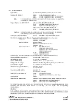
DSD-028 / DSD-036 / DSD2-028 / DSD2-036 


04/2013 

Three-phase-synchronous motor 


English 

Inspection and maintenance 


Working on the electric motor: 


Work must not be carried out on the electric motor until the motor has come to a standstill, 
is  electrically  isolated,  de-pressurized  and  has  cooled  down.  All  connections,  such  as 
screws  on  the  motor  that  were  loosened  must  be  tightened  again  after  the  inspection  and 
maintenance work. 

When carrying out work on the motor, please observe the technical instructions and notes in 
the respective sections in these Commissioning and Maintenance Instructions. 

When carrying out maintenance work, observe all safety instructions which also apply to the 
commissioning of the motor (see Section 4.1). 

Attention!: 
If  the  optional  holding  brake  is  fitted,  this  brake  must  not  perform  a  safety  function  during 
work on the motor (e. g., retaining loads)! 


5.1 

Inspection 

Depending  on the severity  of soiling  on site, cleaning  will have to be carried  out  regularly to guarantee 
the continuous adequate dissipation of heat. The flow rate and the pressure ratio of the cooling system 
must be checked. 

If  an  optional  brake  is  fitted,  wear  limits  are  specified  (e. g.,  maximum  permissible  operating  air  gap, 
maximum  number  of  emergency  braking  operations).  The  actual  degree  of  wear  on  the  brake  must  be 
checked  at  regular  intervals. When  the  permissible  wear  limits  have  been  reached,  the  brake  must  be 
replaced (see Section 5.2). 

If an optional shaft sealing ring is used, it must be checked at regular intervals to ensure it is functioning 
correctly (leakage). 


5.2 

Maintenance 

The  service  life  of  the  bearings  and  sealing  elements  can  differ  greatly  depending  on  the  operating 
conditions, (e. g. operating mode, temperature, speed and load). 

In the case of trouble-free operation, we generally recommend the following maintenance procedures: 

•  Replacement of the bearings after 20.000 running hours (the bearings are designed for a calculated 

service life of 20.000 running hours) 

•  Replacement of the shaft-sealing ring after approximately 5.000 running hours, if present and if no 

leaks have been detected during previous inspections 

If an optional brake is fitted, it is essential that it is replaced when its wear limits are reached. 

The  maintenance  work  is  to  be  undertaken  by  Baumüller  or  a  specialist  organization  authorized  by 
Baumüller. 


Caution! 
The  specifications  of  the  technical  instructions  TABG  30026  must  be  followed  during 
maintenance and servicing on motors which are used for safety-oriented applications. 


Disposal 

The motor must be disposed of in accordance with the relevant national and local regulations within the 
framework of the normal recycling process. 

The encoder electronics (if provided) must be disposed of in the proper manner as electronic scrap. 


Содержание DSD-028

Страница 1: ...28 DSD 036 DSD2 028 DSD2 036 04 2013 Three phase synchronous motor English TAM00721_eng DSD 028 DSD 036 DSD2 028 DSD2 036 Three phase synchronous motor Version 04 2013 English Commissioning and Maintenance Instructions ...

Страница 2: ... owner must pass on this documentation together with the unit machine Following the sale of the unit machine this original and all copies are to be passed on to the purchaser Following disposal or any other form of termination of utilization this original and all copies are to be destroyed With the introduction of this documentation corresponding documentation with earlier issue dates is supersede...

Страница 3: ...ctions 13 4 Commissioning operation 14 4 1 Safety instructions 14 4 2 Checks prior to commissioning 14 4 3 Commissioning operation 15 4 4 Malfunctions in operation 15 5 Inspection and maintenance 17 5 1 Inspection 17 5 2 Maintenance 17 6 Disposal 17 7 Pole assignment main connection and control port 18 7 1 Resolver KTY on power connection 18 7 2 Resolver KTY on signal connection 19 7 3 SRS SRM50 S...

Страница 4: ...ety oriented applications We draw your attention to the following hazards when using the product Hazards resulting from Lifting and transport Electrical power Moving parts Hot surfaces EMC interference Mechanical overload Thermal overload To avoid injury to people and damage to property and to minimise residual risks please read all the safety instructions and in particular those which are marked ...

Страница 5: ...til such time as the conformity of the finished product with this directive has been established refer to EN 60204 1 Electrical Equipment of Machines EMC Directive EC When the electric motor is used as intended its operation must comply with the safety requirements laid down in the EMC Directive EC Proper installation e g physical isolation of signal and power cables shielded wiring and cable etc ...

Страница 6: ...ons unauthorized modifications and changes to the electric motor are not permitted If such modifications changes are necessary please contact the motor manufacturer No safety devices may be dismantled or decommissioned when operating the electric motor 2 Operating conditions 2 1 Product description The DSD and DSD2 series electric motors are 8 pole three phase synchronous motors with rare earth ma...

Страница 7: ...ameplate 1 Manufacturer 2 Standards and approvals 3 Thermal sensor 4 Feedback encoder 5 optional brake voltage 6 optional brake power 7 optional brake holding torque 8 Motor number 9 Article number ID 10 Motor is run with a converter 11 Rated frequency fN 12 Thermal class VDE insulation class 13 Permissible ambient temperature 14 Motor operating mode 15 Motor protection type 16 Motor type designat...

Страница 8: ...oder Option encoder thermal sensor Option Hiperface port 17 pin Option Endat 2 1 8 9 pin Option Endat 2 2 Thermal motor protection EN 60034 11 Thermal sensor KTY84 130 in stator winding Winding insulation EN 60034 1 Thermal class F θ 105 K Ambient temperature 0 C to 40 C standard Altitude EN 60034 1 1 000 m above sea level standard Rolling contact bearings Standard Ball bearing with long term grea...

Страница 9: ... 15 to 60 C for no more than two years Elevated storage temperatures within the framework of the working temperature accelerate the rate at which seals and bearing grease deteriorate and therefore have a negative impact on the service life even before the unit has been commissioned Direct exposure to incident solar radiation UV light and ozone also lead to an ageing of the gaskets and must be avoi...

Страница 10: ... 250 x 10 0 0625 DSD 036 250 x 250 x 10 0 0625 DSD2 028 250 x 250 x 10 0 0625 DSD2 036 250 x 250 x 10 0 0625 Table 1 Mounting surfaces The heat dissipation conditions approve on larger mounting surfaces An insulated mounting of the motors is not permitted 2 7 Balancing output elements vibration Do not subject the shaft or bearings to impacts On mounting and dismounting output elements it is not pe...

Страница 11: ...rque for safety screw S of a belt pulley appropriate measures for securing screw must be applied Vibration The site vibration response of the system which is determined by the output elements the mounting conditions the alignment the installation and the effects of external vibrations may cause the vibration values at the motor to increase In the interest of reliable motor operation and a long bea...

Страница 12: ...oling method employed for the electric motor The motor has to mounted in such a way as to guarantee sufficient waste heat removal via the housing and motor flange surfaces comp Section 2 6 the motor can be mounted and operated with the connection data and fastening features provided The mounting dimensions of the motor and the tolerance details are provided in the technical documentation When moun...

Страница 13: ... the contacts of the encoder or thermal sensor with your hands or with tools which are or may be electrostatically charged The encoder and the thermal sensors are electrostatically sensitive components Electrical installation The person setting up the system is responsible for correct electrical installation The motor data on the nameplate must be observed Connection cables and connectors must be ...

Страница 14: ...tacts and at the motor windings Never touch these modules elements while the motor is in operation Installing and uninstalling safety devices The electric motor must not be commissioned without first mounting the safety devices The motor must be put out of operation when installing and dismantling components and systems which are provided for monitoring the motor for safe operation Danger on physi...

Страница 15: ... Have all output elements been mounted and adjusted in accordance with the manufacturer s instructions Are measures in place to ensure that the maximum permitted speed nmax of the motor cannot be exceeded The maximum permitted speed nmax is the highest permitted operating speed for short time duty Checks during operation Listen out for unusual noises If scraping scratching grinding or other simila...

Страница 16: ...bles Uneven running Insufficient screening on connecting cables Controller parameters too high Check screening connection and grounding Optimise controller parameters Vibrations Coupling element or driven machine poorly balanced Inadequate alignment of the drive train Fixing screws loose Rebalance Realign machine set Check and tighten screwed connections Running noises Foreign bodies in the motor ...

Страница 17: ...e of wear on the brake must be checked at regular intervals When the permissible wear limits have been reached the brake must be replaced see Section 5 2 If an optional shaft sealing ring is used it must be checked at regular intervals to ensure it is functioning correctly leakage 5 2 Maintenance The service life of the bearings and sealing elements can differ greatly depending on the operating co...

Страница 18: ...gled Rotatable Function Receptacle Signal Contact No Schematic Motor U 1 Power 8 Pole Pin Contacts V 3 W 4 PE 2 Brake 1 A B Temp Sensor KTY C KTY D Housing s c Resolver COS 1 Signal 12 Pole Pin Contacts SIN 5 SIN 6 COS 8 REF 10 REF 12 Housing s c Figure 2 Resolver KTY on power connection s c shield connection 1 brake optional see nameplate Schematic view of the contact side D 3 1 C 4 B A 2 3 6 8 4...

Страница 19: ...ceptacle Signal Contact No Schematic Motor U 1 Power 8 Pole Pin Contacts V 3 W 4 PE 2 Brake 1 A B Housing s c Resolver COS 1 Signal 12 Pole Pin Contacts SIN 5 SIN 6 COS 8 REF 10 REF 12 Temp Sensor KTY 7 KTY 9 Housing s c Figure 3 Resolver KTY on signal connection s c shield connection 1 brake optional see nameplate Schematic view of the contact side D 3 1 C 4 B A 2 3 6 8 4 5 1 2 7 9 12 11 10 P ...

Страница 20: ...tion Receptacle Signal Contact No Schematic Motor U 1 Power 8 Pole Pin Contacts V 3 W 4 PE 2 Brake 1 A B Temp Sensor KTY C KTY D Housing s c Hiperface REFCOS 1 Signal 12 Pole Pin Contacts Daten 2 SIN 5 REFSIN 6 Daten 7 COS 8 GND 10 U 12 Housing s c Figure 4 Hiperface port KTY on power connection s c shield connection 1 brake optional see nameplate Schematic view of the contact side D 3 1 C 4 B A 2...

Страница 21: ...tion Receptacle Signal Contact No Schematic Motor U 1 Power 8 Pole Pin Contacts V 3 W 4 PE 2 Brake 1 A B Housing s c Hiperface REFCOS 1 Signal 12 Pole Pin Contacts Daten 2 SIN 5 REFSIN 6 Daten 7 COS 8 GND 10 U 12 Temp Sensor KTY 3 KTY 4 Housing s c Figure 5 Hiperface port KTY on signal connection s c shield connection 1 brake optional see nameplate Schematic view of the contact side D 3 1 C 4 B A ...

Страница 22: ...r English 7 5 ECN1313 EQN 1325 encoder with EnDat 2 1 port from Heidenhain companies M23 17 polig Pin Signal Ansicht auf Kontaktseite der Gerätedose 1 2 3 4 5 6 7 8 9 10 11 12 13 14 15 16 17 Up 0V Up Clock Clock inv 0V B B Data A A Data inv Figure 6 pole assignment ECN 1313 EQN 1325 ...

Страница 23: ...EQN 1337 M12 7 7 ECN1325 EQN 1337 encoder with EnDat 2 2 port from Heidenhain companies M23 9 polig Pin Signal 5 6 8 7 2 3 9 4 1 Ansicht auf Kontaktseite der Gerätedose 1 2 3 4 5 6 7 8 9 Clock Clock inv Up 0V Data Data inv Sensor Up Sensor 0V Figure 8 pole assignment ECN 1325 EQN 1337 M23 Note For other encoder types and optional lead for the temperature sensor via the encoder cable see the enclos...

Страница 24: ...ualified personnel overloaded the system operated the system with o faulty safety devices o safety devices that were incorrectly fitted or not fitted o safety devices or protective devices that are not in working order not operated the system in the stipulated ambient conditions You have modified the system without the written approval of Baumüller Nürnberg GmbH You have not observed the instructi...

Отзывы: