


TAM00721
11
DSD-028 / DSD-036 / DSD2-028 / DSD2-036
04/2013
Three-phase-synchronous motor
English
Attention:
•
On shaft versions without a key, the output elements are to be fastened to the output shaft with the
aid of suitable clamping sets.
•
On shaft versions with a key, it must be ensured that the output elements rest on the shaft
shoulder. Note: The chamfer or radius on the output element and the shaft radius on the shoulder
must be matched.
•
Is the tapped hole in the end of the shaft used for axial securing of output elements (e. g. belt pulley),
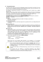
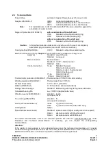
the maximum tightening torque acc. to following table 2 must not be exceeded.
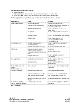
thread
tightening torque
in Nm
M5
2,2
M8
10,0
M10
19,0
M12
33,0
Table 2: Tightening torque for safety screw S of a belt pulley
appropriate measures for securing screw must be applied
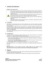
Vibration:
The site vibration response of the system, which is determined by the output elements, the
mounting conditions, the alignment, the installation, and the effects of external vibrations,
may cause the vibration values at the motor to increase.
In the interest of reliable motor operation and a long bearing service life, the permitted
vibration values in accordance with EN 60034-14 should not be exceeded. Under certain
circumstances, the rotor may need to be fully balanced with the output element (in
accordance with ISO 140).
The vibration value after mounting must not exceed the permitted rates of acceleration
(comp. Section 2.4 )
Where there are deviations from normal operation – e. g., rise in temperature, noises,
vibration – switch off the motor. Identify the cause and, if necessary, contact the
manufacturer.
S