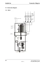

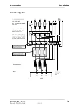

Connection Diagram
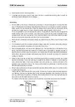
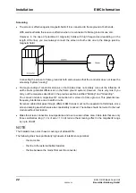
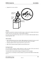
Installation
BUG 3/2/20 Basic Feed Unit
27
Baumüller Nürnberg GmbH
5.96064.02
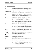
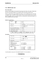
5.3.4 Connection Information
F1
Line protection in accordance with VDE 0100, slow-blowing fuse of 2-3 times
the transformer's rated current or motor protection switch in systems with only
one axis.
Current-operated e.l.c.b.
The principles on which the power converter and the motor work lead to rela-
tively high leakage currents to earth, i.e. the drive may be incompatible with
current-operated e.l.c.b. systems. For configuration, take into account provisional
standard EN 50178:1994 Section 5.2.11.
T1
Autotransformer YNO or isolating transformer Yny0; inrush current limitation
device depending on the type and power of the transformer. For further details,
refer to Transformer Accessories
T2
Isolating transformer for additional feed of the auxiliary controller supply
BUG 2 and 3: isolating transformer 230/230, 160 VA,
No. 1900 7153
BUG 20:
isolating transformer 230/230, 250 VA,
No. 1900 7176
With this option, error messages are retained even if K1 has dropped. The op-
tion is not necessary for operation. Use one transformer per basic unit.
K1
Mains contactor with auxiliary contact for controller enable
K2, R2
Starting current limitation prevents the B6 rectifier's permissible non-repetitive
peak current, I
ON
, from being exceeded; the contactor shunts out resistors
R = 10
Ω
/50 W after one second; this is
always
necessary when using capaci-
tor unit BUK, otherwise only with transformers T
1
rated at 5 kVA and above;
available as a complete module designated WSV (chapter 5.4.2)
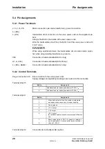
L+, L-
ZK+, ZK-
Intermediate circuit connection to the BUS units via the supplied busbars.
With several servo units, arrange the BUG in the middle.
Wire the BUG 3 with 4 mm² wires.
DANGER
When using autotransformers, the intermediate circuit carries mains potential;
When using isolating transformers, ground L- (ZK-).
L1, L2, L3, PE
Cross-section according to EN 60204-1:1992
For line-laying, refer to EMC Information
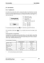
R
B
Drives that have a very high centrifugal mass or acceleration/braking drives are
run with external ballast. For more information, refer to the section entitled BUR
Resistor Unit.
BUG 3: Connection of an external ballast resistor rated at 10
Ω
or above be-
tween ballast and L+.
BUG 2: Connection of an external ballast resistor rated at 8
Ω
or above on
connector X69 on the top of the device.
BUG 20: Connection of an external ballast resistor rated at 4
Ω
or above be-
tween A1 and ZK+.
Содержание BUG 2
Страница 8: ...Abbreviations IV BUG 3 2 20 Basic Feed Unit 5 96064 02 Baumüller Nürnberg GmbH ...
Страница 12: ...Safety Information 4 BUG 3 2 20 Basic Feed Unit 5 96064 02 Baumüller Nürnberg GmbH ...
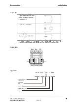
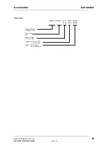
Страница 18: ...Technical Data Type Code 10 BUG 3 2 20 Basic Feed Unit 5 96064 02 Baumüller Nürnberg GmbH 2 3 Type Code ...
Страница 20: ...Transport Unpacking 12 BUG 3 2 20 Basic Feed Unit 5 96064 02 Baumüller Nürnberg GmbH ...
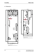
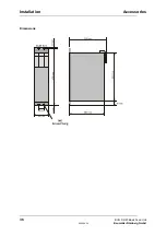
Страница 22: ...Assembly Dimensions 14 BUG 3 2 20 Basic Feed Unit 5 96064 02 Baumüller Nürnberg GmbH 4 1 Dimensions ...
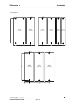
Страница 23: ...Dimensions Assembly BUG 3 2 20 Basic Feed Unit 15 Baumüller Nürnberg GmbH 5 96064 02 Fastening Holes ...
Страница 33: ...Connection Diagram Installation BUG 3 2 20 Basic Feed Unit 25 Baumüller Nürnberg GmbH 5 96064 02 5 3 2 BUG 2 ...
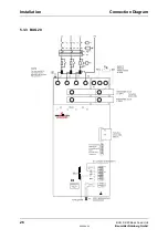
Страница 34: ...Installation Connection Diagram 26 BUG 3 2 20 Basic Feed Unit 5 96064 02 Baumüller Nürnberg GmbH 5 3 3 BUG 20 ...
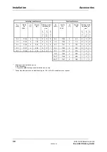
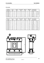
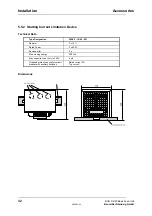
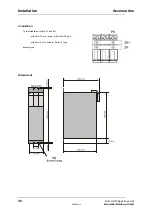
Страница 44: ...Installation Accessories 36 BUG 3 2 20 Basic Feed Unit 5 96064 02 Baumüller Nürnberg GmbH Dimensions ...
Страница 48: ...Installation Accessories 40 BUG 3 2 20 Basic Feed Unit 5 96064 02 Baumüller Nürnberg GmbH ...