background image

41

8.1.4  Fixed Pattern Noise Correction (FPNC)

CMOS sensors exhibit nonuniformities that are often called fixed pattern noise (FPN). 

However it is no noise but a fixed variation from pixel to pixel that can be corrected. The 

advantage of using this correction is a more homogeneous picture which may simplify the 

image analysis. Variations from pixel to pixel of the dark signal are called dark signal non-

uniformity (DSNU) whereas photo response nonuniformity (PRNU) describes variations 

of the sensitivity. DNSU is corrected via an offset while PRNU is corrected by a factor.

The correction is based on columns. It is important that the correction values are comput-

ed for the used sensor readout configuration. During camera production this is derived for 

the factory defaults. If other settings are used (e.g. different number of readout channels) 

using this correction with the default data set may degrade the image quality. In this case 

the user may derive a specific data set for the used setup.

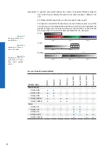
FPN Correction Off

FPN Correction On

8.1.4.1  VEXG

Camera Type

FPNC

Monochrome

VEXG-02M

VEXG-13M

VEXG-25M

VEXG-52M.R

VEXG-100M.R

Color

VEXG-02C

VEXG-13C

VEXG-25C

VEXG-52C.R

VEXG-100C.R

8.1.4.2  VEXU

Notice

On cameras with Sony sensors additional FPN correction is not necessary.

Camera Type

FPNC

Monochrome

VEXU-24M 

Color

VEXU-24C

Содержание VEXG

Страница 1: ...User s Guide VEXG Gigabit Ethernet VEXU USB 3 0 Document Version v1 5 Release 25 10 2018 Document Number 11165414 ...

Страница 2: ...2 ...

Страница 3: ... 6 1 2 Power Supply and Digital IOs 20 6 1 3 Digital IO 20 6 1 4 LED Signaling 20 6 2 VEXU 21 6 2 1 USB 3 0 Interface 21 6 2 2 Digital IOs 21 6 2 3 Digital IO 21 6 2 4 LED Signaling 22 7 Product Specifications 23 7 1 Sensor Specifications 23 7 1 1 Spectral Sensitivity 23 7 1 2 Sensor Shutter Mode only cameras with Rolling Shutter sensors 25 7 2 Field of View Position 27 7 2 1 VEXG 27 7 2 2 VEXU 27...

Страница 4: ...uits VEXG 52 8 4 3 IO Circuits VEXU 52 8 4 4 Trigger 53 8 4 5 Trigger Source 53 8 4 6 Debouncer 54 8 4 7 ExposureActive Flash Signal 55 8 4 8 Frame Counter 56 8 5 Device Reset 56 8 6 User Sets 56 8 6 1 VEXG 56 8 6 2 VEXU 57 8 7 Factory Settings 57 8 8 Timestamp 57 8 9 Start Stop Behaviour 58 8 9 1 Start Stop Abort Acquisition Camera 58 8 9 2 Start Stop Interface 58 9 VEXG Interface Functionalities...

Страница 5: ... 9 6 1 Normal Case 64 9 6 2 Fault 1 Lost Packet within Data Stream 64 9 6 3 Fault 2 Lost Packet at the End of the Data Stream 65 9 6 4 Termination Conditions 65 10 VEXU Interface Functionalities 66 10 1 Device Information 66 ...

Страница 6: ...port cameras baumer com Target group for this User s Guide This User s Guide is aimed at experienced users which want to integrate camera s into a vision system Intended Use The camera is used to capture images that can be transferred over a GigE interface VCXG or a USB 3 0 interface VCXU to a PC Classification of the safety instructions In the User s Guide the safety instructions are classified a...

Страница 7: ...ironment The return of the packaging to the material cycle helps conserve raw mate rials an reduces the production of waste When no longer required dispose of the packaging materials in accordance with the local regulations in force Keep the original packaging during the warranty period in order to be able to pack the device properly in the event of a warranty claim Warranty Notes If it is obvious...

Страница 8: ... for proper heat dissipation but suggest the following principles operate the cameras only in mounted condition mounting in combination with forced convection may provide proper heat dissipation Caution Observe precautions for handling electrostatic sensitive devices Caution Class A The camera is a class A device DIN EN 55022 2011 It can cause radio interference in residential environments Should ...

Страница 9: ... Software Development Kit SDK with sample codes and help files for simple integration Baumer viewer for all camera functions GenICam compliant XML file to describe the camera functions Supplied with installation program with automatic camera recognition for simple commissioning Compact design Light weight flexible assembly Reliable operation State of the art camera electronics and precision mechan...

Страница 10: ...XG Product Article No Registration No Date of Registration Monochrome VEXG 52M R 11185978 R REI BkR VEXG 52MR 2018 07 10 VEXG 100M R 11185979 R REI BkR VEXG 100MR 2018 07 10 Color VEXG 52C R 11185977 R REI BkR VEXG 52MR 2018 07 10 VEXG 100C R 11185990 R REI BkR VEXG 100MR 2018 07 10 ...

Страница 11: ...o Description No Description 1 Lens mount CS Mount 3 Ethernet Port Signaling LED s 2 Power supply Digital IO 3 2 VEXU 2 4 3 1 No Description No Description 1 Lens mount CS Mount 3 USB 3 0 port 2 Digital IO 4 Signaling LED ...

Страница 12: ... 2 3 1920 1200 41 VEXG 52M R 1 2 5 2592 1944 14 VEXG 100M R 1 2 3 3856 2764 7 Color VEXG 02C 1 4 640 480 217 VEXG 13C 1 2 1280 1024 61 VEXG 25C 2 3 1920 1200 41 VEXG 52C R 1 2 5 2592 1944 14 VEXG 100C R 1 2 3 3856 2764 7 Dimensions 29 29 20 20 4 45 7 2 8 7 20 3 28 7 20 22 40 CS mount 1 55 0 35 48 9 8 9 3 8 x M3 x 4 2 x M3 x 4 ø 1 3 0 35 VEXG 52 VEXG 100 ...

Страница 13: ...e Sensor Size Resolution Full Frames max fps Monochrome VEXU 24M 1 1 2 1920 1200 38 Color VEXU 24C 1 1 2 1920 1200 38 Dimensions 29 29 20 18 6 15 8 2 6 20 3 28 7 20 22 30 CS mount 1 55 0 35 37 8 8 4 3 8 x M3 x 4 2 x M3 x 4 ø ...

Страница 14: ...can damage the camera Provide adequate dissipation of heat to en sure that the temperatures does not exceed the values in the table below As there are num erous possibilities for installation Baumer recommends no specific method for proper heat dissipation but suggest the following principles operate the cameras only in mounted condition mounting in combination with forced convection may provide p...

Страница 15: ...n mounting the lens to the device Therefore the following points are very important Install the camera in an environment that is as dust free as possible Keep the dust cover bag on camera as long as possible Hold the camera downwards with unprotected sensor Avoid contact with any optical surface of the camera ...

Страница 16: ...lder 2 2 Turn the filter holder 2 until the guide tabs can be seen in the guide grooves 4 3 Remove the filter holder 2 4 Carefully remove the existing filter 3 Do not touch the sensor 5 Insert the new filter into the sensor opening 6 Put the filter holder 2 back in 7 Turn the filter holder 2 until the guide tabs cannot be seen in the guide grooves 4 5 5 Cleaning Filter Cover glass Notice The senso...

Страница 17: ...ine thinner for cleaning To clean the surface of the camera housing use a soft dry cloth To remove persistent stains use a soft cloth dampened with a small quantity of neutral detergent then wipe dry 5 6 Transport Storage Transport the camera only in the original packaging When the camera is not installed then storage the camera in original packaging ...

Страница 18: ... Amplitude under neath crossover frequencies 1 5 mm Acceleration 10 g Test duration Axis 150 min Vibration broad band IEC 60068 2 64 Frequency range 20 1000 Hz Acceleration RMS 10 g Test duration Axis 300 min Shock IEC 60068 2 27 Puls time 11 ms 6 ms Acceleration 50 g 100 g Bump IEC60068 2 29 Pulse Time 2 ms Acceleration 100 g ...

Страница 19: ...e negative Vport 4 blue MX3 5 blue white MX3 6 orange MX2 positive negative Vport 7 brown white MX4 8 brown MX4 Dimension Free Connector cable Type090 From overmold to plug stop A1 9 0mm 0 50 0 00 From overmold to tip of thumbscrews B1 4 25mm 1 00 0 25 Dimension Fixed Connector camera Type090 From contact point to plug stop A2 9 0mm 0 00 1 00 From contact point to bottom of thumbscrew thread B2 4 ...

Страница 20: ... Line0 white 4 OUT1 Line1 black Power Supply Power Supply VCC 12 24 VDC 20 6 1 3 Digital IO Input Output Pin 2 IN1 FPGA FPGA Pin 3 GND Pin 1 Power VCC Pin 4 OUT RL 12 24 VDC 20 Pin 3 GND 6 1 4 LED Signaling 2 1 LED Signal Meaning 1 green static link active green flash receiving 2 yellow static error yellow flash transmitting Figure 2 LED positions on Bau mer VEXG cameras ...

Страница 21: ...D 9 MicB_SSRX 5 GND 10 MicB_SSRX 6 2 2 Digital IOs Power Supply Digital IOs on camera side wire colors of the connecting cable ordered separately 1 2 4 3 1 Power IO brown 3 GND blue 2 IN1 Line0 white 4 OUT1 Line1 black 6 2 3 Digital IO Input Output Pin 2 IN1 FPGA FPGA Pin 3 GND Pin 1 Power IO Pin 4 OUT RL 5 20 VDC 20 Pin 3 GND ...

Страница 22: ...22 6 2 4 LED Signaling LED Signal Meaning LED green flash Power on green USB 3 0 connection red USB 2 0 connection yellow Readout active red flash Update Figure 3 LED position on Bau mer VEXU camera ...

Страница 23: ...00 1200 Transmission wavelength in nm Filter glass of color cameras Wave Length nm VEXG 02M Python 300 0 1000 2000 3000 4000 5000 6000 300 400 500 600 700 800 900 1000 1100 Response V s W m 2 Wave Length nm VEXG 02C Python 300 0 1000 2000 3000 4000 5000 6000 300 400 500 600 700 800 900 1000 1100 Response V s W m 2 Wave Length nm VEXG 13M Python 1300 0 1000 2000 3000 4000 5000 6000 300 400 500 600 ...

Страница 24: ... 1100 0 0 10 0 20 0 30 0 40 0 50 0 60 0 70 0 Quantum Efficiency Wave Length nm VEXG 52C R MT9P031 300 400 500 600 700 800 900 1000 1100 0 0 10 0 20 0 30 0 40 0 50 0 60 0 70 0 Quantum Efficiency Wave Length nm VEXG 100M R MT9J003 300 400 500 600 700 800 900 1000 1100 0 0 10 0 20 0 30 0 40 0 50 0 60 0 70 0 Quantum Efficiency 400 450 500 550 600 650 700 VEXG 100C R MT9J003 Wave Length nm 0 0 10 0 20 ...

Страница 25: ...eset Non overlapped Rolling Overlapped 7 1 2 1 Global Reset Shutter Trigger Line 1 Exposure Readout Time Line 2 Line 3 Line 4 Line 5 Line 6 Line 7 Line n Line n 3 Line n 2 Line n 1 tTriggerDelay For cameras with rolling shutter sensor and set shutter mode Global Reset for each frame all of the lines start exposure at the same time but the end of exposure is delayed by the offset of the previous li...

Страница 26: ...t and end times are staggered Data readout for each line begins immediately following the line s exposure The readout time for each line is the same but the start and end times are staggered One advantage of a Rolling Shutter is increased sensitivity However because exposure starts at different times throughout the frame there are known artifacts such as skew wobble and partial exposure Notice Due...

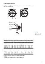
Страница 27: ... VEXG 02 0 04 0 04 0 04 0 04 12 50 0 100 0 6 11 6 0 55 VEXG 13 0 04 0 04 0 04 0 04 12 50 0 100 0 6 11 6 0 55 VEXG 25 0 05 0 05 0 05 0 05 17 65 0 070 0 6 16 5 0 55 VEXG 52 0 06 0 06 0 06 0 06 12 5 0 100 0 6 12 35 0 4 VEXG 100 0 06 0 06 0 06 0 06 12 5 0 100 0 6 12 35 0 4 7 2 2 VEXU Camera Type xM mm yM mm xR mm YR mm ztyp mm αtyp A mm D mm VEXU 24 0 04 0 04 0 04 0 04 12 58 0 065 0 4 10 8 0 50 typica...

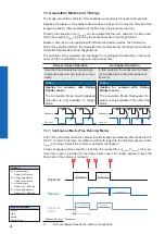
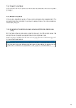
Страница 28: ...verlapped Operation is only available in Trigger Mode In this operation the exposure of a frame n 1 takes place during the readout of frame n Notice Applies for cameras with Rolling Shutter sensor The Acquisition Mode Overlapped Op eration is only available in Free Running Mode Exposure Readout Exposure Readout 7 3 1 Continuous Mode Free Running Mode In the Free Running mode the camera records ima...

Страница 29: ...ically stopped 7 3 4 Acquisition Frame Rate except cameras with Rolling Shutter sen sors With this feature Baumer introduces a clever technique to the VEX camera series that enables the user to predefine a desired frame rate in continuous mode For the employment of this mode the cameras are equipped with an internal clock genera tor that creates trigger pulses Notice From a certain frame rate skip...

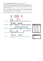
Страница 30: ...n 1 texposure n treadout n texposure n 1 texposure treadout 3 tearliestpossibletrigger n 1 texposure n 4 tnotready n 1 texposure n VEXG only cameras with Rolling Shutter sensor The sensor shutter mode depends on the Trigger Mode Camera Type Sensor Trigger Mode On Trigger Mode Off Monochrome Shutter Mode Readout Mode Shutter Mode Readout Mode VEXG 52M R Global Reset Non overlapped Rolling Overlappe...

Страница 31: ...adout n and exposure time of the next image texposure n 1 It can be determined by the formulas mentioned above no 1 or 3 as is the case In case of identical exposure times tnotready remains the same from acquisition to acquisi tion Exposure Readout texposure n treadout n 1 treadout n texposure n 1 ttriggerdelay tmin Trigger Exposure Active tExposure Active n tExposureDelay tExposure Active n 1 Tri...

Страница 32: ...rmulas mentioned above no 2 or 4 as is the case Exposure Readout texposure n treadout n 1 treadout n texposure n 1 texposure n 2 ttriggerdelay tmin Trigger Exposure Active tExposure Active n tExposureActiveDelay tExposure Active n 1 TriggerReady tnotready Image parameters Offset Gain Mode Partial Scan Timings A exposure time frame n effective B image parameters frame n effective C exposure time fr...

Страница 33: ... will be skipped Exposure Readout texposure n treadout n 1 treadout n texposure n 1 texposure n 2 ttriggerdelay tmin Trigger Exposure Active tExposure Active n tExposureActiveDelay tExposure Active n 1 TriggerReady tnotready Notice From a certain frequency of the trigger signal skipping triggers is unavoidable In gen eral this frequency depends on the combination of exposure and readout times Imag...

Страница 34: ...e Readout texposure n treadout n 1 treadout n texposure n 1 ttriggerdelay tmin Trigger Exposure Active tExposure Active n tExposureActiveDelay tExposure Active n 1 TriggerReady tnotready Image parameters Offset Gain Mode Partial Scan Timings A exposure time frame n effective B image parameters frame n effective C exposure time frame n 1 effective D image parameters frame n 1 effective E earliest p...

Страница 35: ...uch as C C and the NET Framework on Windows as well as Mono on Linux operating systems which offers the use of other languages such as e g C or VB NET More information can be found at http www baumer com id 8453 7 4 2 3rd Party Software Strict compliance with the GenICam standard allows Baumer to offer the use of 3rd Party Software for operation with cameras of this series You can find a current l...

Страница 36: ...eras the image format on Baumer cameras not only in cludes resolution but a set of predefined parameter These parameters are Resolution horizontal and vertical dimensions in pixels Binning Mode 8 1 1 1 VEXG Camera Type Full frame Binning 2x2 Binning 2x1 Binning 1x2 Monochrome VEXG 02M VEXG 13M VEXG 25M VEXG 52M R VEXG 100M R Color VEXG 02C VEXG 13C VEXG 25C VEXG 52C R VEXG 100C R 8 1 1 2 VEXU Came...

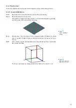
Страница 37: ...tern generally in a 50 green 25 red and 25 blue array Mono Monochrome The color range of mono images consists of shades of a single color In general shades of gray or black and white are synonyms for mono chrome RGB Color model in which all detectable colors are defined by three coordinates Red Green and Blue Red Green Blue Black White The three coordinates are displayed within the buffer in the o...

Страница 38: ...to Baumer VEX cameras In this formats the unused bits of one pixel are filled with data from the next pixel 8 bit Byte 1 Byte 2 Byte 3 12 bit Byte 1 Byte 2 unused bits Packed Byte 1 Byte 2 Byte 3 Pixel 0 Pixel 1 8 1 2 2 Pixel Formats VEXG Camera Type Mono8 Mono10 Mono12 Mono12p Bayer RG8 Bayer RG10 Bayer RG12 Bayer RG129 Monochrome VEXG 02M VEXG 13M VEXG 25M VEXG 52M R VEXG 100M R Color VEXG 02C V...

Страница 39: ...39 8 1 2 3 Pixel Formats VEXU Camera Type Mono8 Mono12 Bayer RG8 Bayer RG12 Monochrome VEXU 24M Color VEXU 24C ...

Страница 40: ...n the following ranges step size 1μsec 8 1 3 1 VEXG Camera Type texposure min texposure max Monochrome VEXG 02M 40 μsec 1 sec VEXG 13M 40 μsec 1 sec VEXG 25M 40 μsec 1 sec VEXG 52M R 20 μsec 1 sec VEXG 100M R 48 μsec 1 sec Color VEXG 02C 40 μsec 1 sec VEXG 13C 40 μsec 1 sec VEXG 25C 40 μsec 1 sec VEXG 52C R 20 μsec 1 sec VEXG 100C R 48 μsec 1 sec 8 1 3 2 VEXU Camera Type texposure min texposure ma...

Страница 41: ...y a factor The correction is based on columns It is important that the correction values are comput ed for the used sensor readout configuration During camera production this is derived for the factory defaults If other settings are used e g different number of readout channels using this correction with the default data set may degrade the image quality In this case the user may derive a specific...

Страница 42: ...Size X horizontal size of the ROI Size Y vertical size of the ROI Notice For color binning and a defined region of interest the setting of an odd number for the offset is possible This would lead to a pixel offset and consequently to false colors This is prevented by performing the offset on an image without binning Binning is then performed to this result 8 1 5 1 ROI Start ROI End ROI ROI Readout...

Страница 43: ...nning vertically or horizontally neighboring pixels are aggregated and reported to the software as one single superpixel In bidirectional binning a square of neighboring pixels is aggregated Notice Occuring deviations in brightness after binning can be corrected with Brightness Correction function 8 1 6 1 Monochrome Binning Binning Illustration Output without 1x2 2x1 2x2 Figure 19 Full frame image...

Страница 44: ...ame color are combined Binning Illustration without 1x2 2x1 2x2 Figure 23 Full frame image no binning of pixels Figure 24 Vertical binning causes a vertically compressed image with doubled brightness Figure 25 Horizontal binning causes a horizontally compressed image with doubled brightness Figure 26 Bidirectional binning causes both a hori zontally and vertically compressed image with quadruple b...

Страница 45: ...hin the sensor binning correction also takes place here A possible overload is prevented by halving the exposure time 2x1 2x1 binning takes place within the FPGA of the camera The binning cor rection is realized by aggregating the charge quantities and then halving this sum 2x2 2x2 binning is a combination of the above versions Charge quantity Binning 2x2 Super pixel Total charge quantity of the 4...

Страница 46: ...ra Type Black Level Monochrome VEXG 02M 0 63 DN10 VEXG 13M 0 63 DN10 VEXG 25M 0 63 DN10 VEXG 52M R 0 255 DN12 VEXG 100M R 0 255 DN12 Color VEXG 02C 0 63 DN10 VEXG 13C 0 63 DN10 VEXG 25M 0 63 DN10 VEXG 52C R 0 255 DN12 VEXG 100C R 0 255 DN12 8 2 1 2 VEXU Camera Type Black Level Monochrome VEXU 24M 0 255 DN12 Color VEXU 24C 0 255 DN12 ...

Страница 47: ... amplified by a user defined gain factor within the camera This gain factor is adjustable Notice Increasing the gain factor causes an increase of image noise 8 2 2 1 VEXG Camera Type Gain dB Monochrome VEXG 02M 0 12 VEXG 13M 0 12 VEXG 25M 0 12 VEXG 52M R 0 12 VEXG 100M R 0 12 Color VEXG 02C 0 12 VEXG 13C 0 12 VEXG 25C 0 12 VEXG 52C R 0 12 VEXG 100C R 0 12 8 2 2 2 VEXU Camera Type Gain dB Monochrom...

Страница 48: ... is unavoidable and intrinsic to the manufacturing and aging process of the sensors The operation of the camera is not affected by these pixels They only appear as brighter warm pixel or darker cold pixel spot in the recorded image Warm Pixel Cold Pixel Charge quantity Normal Pixel Charge quantity Cold Pixel Charge quantity Warm Pixel Figure 28 Distinction of hot and cold pixels within the recorde...

Страница 49: ...l The correction is able to correct up to two neighboring defect pixels Defect Pixels Average Value Corrected Pixels 8 3 3 Add Defect Pixel to Defect pixel list As stated previously this list is determined within the production process of Baumer cam eras and stored in the factory settings Additional hot or cold pixels can develop during the lifecycle of a camera In this case Baumer offers the poss...

Страница 50: ...ixel Keep the mouse pointer over the defect pixel The coordinates of the defect pixel is displayed in the status bar For simplification you can enlarge the image 5 Enter the determined coordinates for X Defect Pixel List Entry PosX and Y Defect Pixel List Entry PosY 6 Activate the registered Defect Pixel List Index Defect Pixel List Entry Active True 7 Stop the camera and start them again to take ...

Страница 51: ...he compliance with predetermined high and low levels only the optical input IN1 0 0 0 8V low 3 3 30V high The defined signals will have no direct effect but can be analyzed and processed on the software side and used to control the camera On the software side the signal is named Trigger Input Line 0 Trigger state high state low state selection inverter Figure 30 Input Signal ...

Страница 52: ...ExposureActive Signals Output Line 1 state high state low IO Matrix state selection software side signal selection software side 8 4 2 IO Circuits VEXG Input Output Pin 2 IN1 FPGA FPGA Pin 3 GND Pin 1 Power VCC Pin 4 OUT RL 12 24 VDC 20 Pin 3 GND 8 4 3 IO Circuits VEXU Input Output Pin 2 IN1 FPGA FPGA Pin 3 GND Pin 1 Power IO Pin 4 OUT RL 5 20 VDC 20 Pin 3 GND Figure 31 IO matrix ...

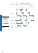
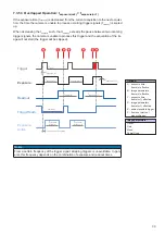
Страница 53: ...ftware trigg e r Hardware trigger VEXU VEXG Each trigger source has to be activated separately When the trigger mode is activated the hardware trigger is activated by default Figure 32 Trigger signal valid for Baumer cameras high low U t 0 0 8V 3 3V 30V Figure 33 Camera in trigger mode A Trigger delay B Exposure time C Readout time Trigger Delay The trigger delay is a flexible user defined delay b...

Страница 54: ...stable by the user If the signal value falls to state low and does not rise within tDebounceLow this is recognized as end of the signal The debouncing times tDebounceHigh and tDebounceLow are adjustable from 0 to 5 msec in steps of 1 μsec low high U t 0 0 3V 3 3V 30V low high U t 0 0 3V 3 3V 30V t t1 tx high time of the signal tDebounceHigh user defined debouncer delay for state high tDebounceLow ...

Страница 55: ...Shutter Mode only cameras with Rolling Shutter sensors the ExposureActive signal is active at different times Sensor Shutter Mode Global Reset Shutter Line 1 Exposure Readout Time Line 2 Line 3 Line 4 Line 5 Line 6 Line 7 Line n Line n 3 Line n 2 Line n 1 Trigger ExposureActive tTriggerDelay jitter possible Shading of extraneous light necessary Sensor Shutter Mode Rolling Shutter Shutter Trigger L...

Страница 56: ...ecific and can con tain any user definable parameters The user set are stored within the camera and can be loaded saved and transferred to other cameras of the EX series By employing a so called user set default selector the user set can be selected as de fault which means the camera starts up with these adjusted parameters 8 6 1 VEXG Parameter AcquisitionMode LineDebouncerLowTimeAbs AcquisitionFr...

Страница 57: ...rnGeneratorSelector BlackLevel TestPattern BrightnessCorrection DefectPixelCorrection 8 7 Factory Settings The factory settings are stored in user set 0 which is the default user set This is the only user set that is not editable 8 8 Timestamp The Timestamp is 64 bits long and reports the current value of the device timestamp counter in nanoseconds Any image or event includes its corresponding tim...

Страница 58: ... readout the current readout will be finished before stopping the camera If the stop signal arrives within an exposure this will be aborted Abort Acquisition The acquisition abort represents a special case of stopping the current acquisition When an exposure is running the exposure is aborted immediately and the image is not read out 8 9 2 Start Stop Interface Without starting the interface transm...

Страница 59: ...an be handled by all network com ponents involved In principle modern network hardware supports a packet size of 1500 Byte which is specified in the GigE network standard Jumboframes merely characterizes a packet size exceeding 1500 Bytes Baumer EXG cameras can handle a MTU of up to 65535 Bytes 9 3 Inter Packet Gap IPG To achieve optimal results in image transfer several Ethernet specific factors ...

Страница 60: ... lead to a loss of packets These lost packets can however be saved by employing an appropriate resend mechanism but this leads to additional load on the network components 9 3 2 Example 2 Multi Camera Operation Optimal IPG A better method is to increase the IPG to a size of optimal IPG number of cameras 1 packet size 2 minimal IPG In this way both data packets can be transferred successively zippe...

Страница 61: ... an intelligent network node an IGMP Internet Group Management Protocol capable Switch or Router and distributed to the receiver group with the specific address range In the example on the figure below multicast is used to process image and message data separately on two differents PC s Multicast Addresses For multicasting Bau mer suggests an adress range from 232 0 1 0 to 232 255 255 255 Figure 3...

Страница 62: ...s IP addresses sub net masks and gateways This process takes up to 12 sec Oncethedevice client isconnectedtoaDHCP enablednetwork fourstepsareprocessed DHCP Discovery In order to find a DHCP server the client sends a so called DHCPDISCOVER broad cast to the network DHCP Offer After reception of this broadcast the DHCP server will answer the request by an unicast known as DHCPOFFER This message cont...

Страница 63: ...d above Once an address is chosen this is sent together with an ARP Address Resolution Pro tocol query to the network to to check if it already exists Depending on the response the IP address will be assigned to the device if not existing or the process is repeated This method may take some time the GigE Vision standard stipulates that establishing connection in the LLA should not take longer than...

Страница 64: ...t order from the camera to the PC The probability of this happening is more then 99 9 6 2 Fault 1 Lost Packet within Data Stream If one or more packets are lost within the data stream this is detected by the fact that packet number n is not followed by packet number n 1 In this case the application sends a resend request A Following this request the camera sends the next packet and then resends B ...

Страница 65: ...packets from no 3 to no 5 are lost This fault is detected after the pre defined time has elapsed and the resend request A is triggered The camera then re sends packets no 3 to no 5 B to complete the image transfer 9 6 4 Termination Conditions The resend mechanism will continue until all packets have reached the pc the maximum of resend repetitions is reached the resend timeout has occured or the c...

Страница 66: ...s part of the camera s USB descriptor Included information Product ID PID Vendor ID VID Model Name Baumer USB Vendor ID Hexadecimal Baumer USB Product ID Hexadecimal VEXU 24M 2825 0126 VEXU 24C 2825 0127 General Unique Identifier GUID Device vendor name Manufacturer Serial number iSerialNumber ...

Страница 67: ...67 ...
Страница 68: ...454 Radeberg Germany Phone 49 0 3528 4386 0 Fax 49 0 3528 4386 86 sales baumeroptronic com www baumer com Technical data has been fully checked but accuracy of printed matter not guaranteed Subject to change without notice Printed in Germany ...

Отзывы: